
Some of you may know that I used to work for the Children's Museum of Bozeman. I oversaw their STEAMlab when it was just getting started. I helped develop curriculum, built cool projects and helped select and install many of the cool gadgets they have in the lab, from network equipment and laptops, to 3D printers, Arduino kits and more. I still try to help out at the museum however I can and I was thrilled when they approached me to help them with a new exhibit.
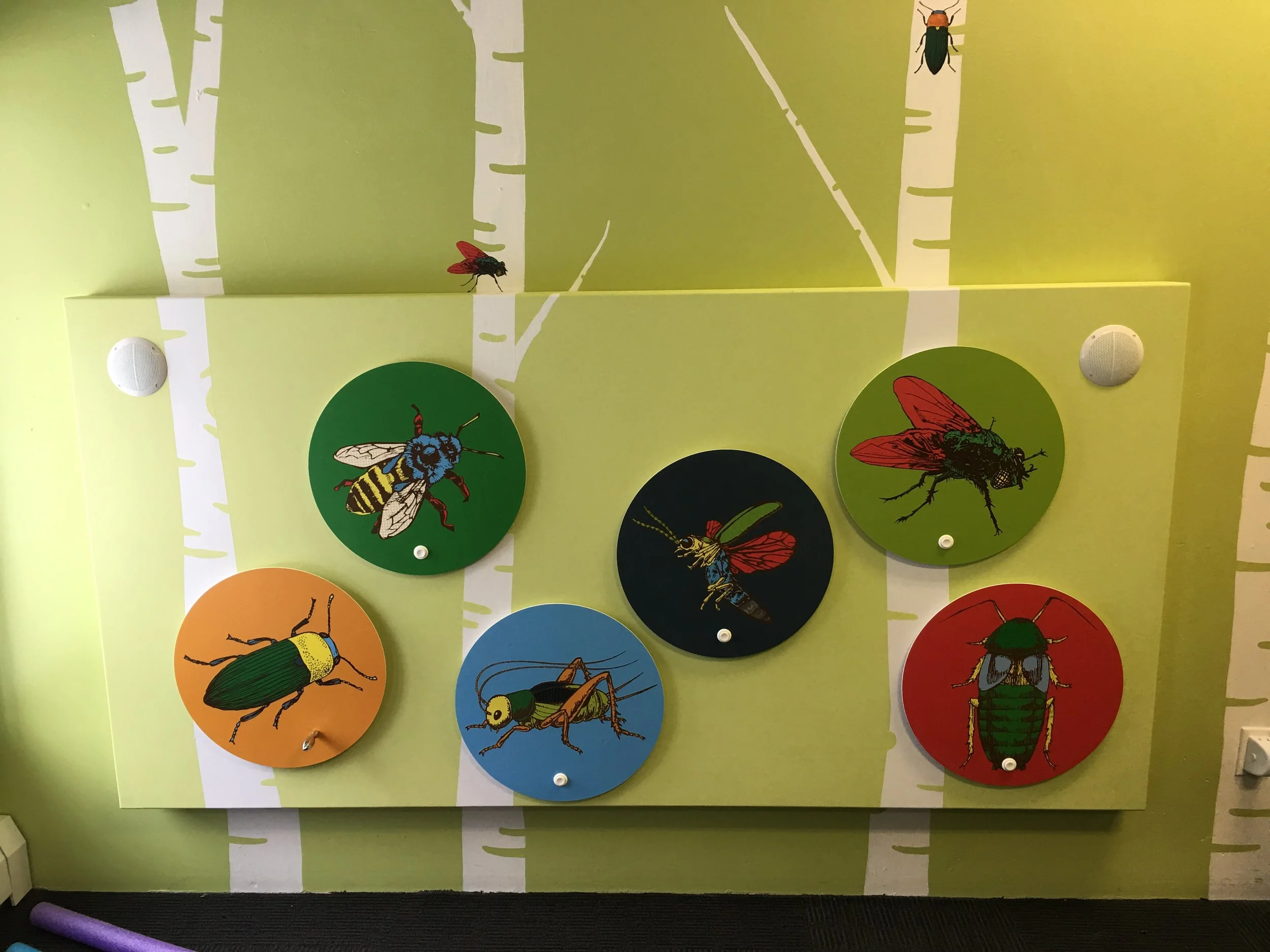
It’s a Bug’s World is all about bugs. Kids can see live bugs, dress up as a bug and play in a large grass "forest", and race little mechanical hex bugs through a maze. What they wanted from me was an interactive wall with 5-6 different bug signs on it that would play the sound they make when touched and potentially light up. They wanted one of the signs to be a click beetle that was motorized to spin when touched. The exhibit will be up for at least a year, so it needed to be able to withstand the abuse of kids.
I experimented with capacitive touch sensors and LED strips that would go around each sign. After a couple demos, we decided to go with large arcade buttons rather than capacitive touch sensors to trigger the sounds and to limit the LEDs to a single firefly sign. The motorized click beetle seemed like a little much, so after some discussion we decided to go with a turn table that the kids could rotate themselves that would trigger the click beetle sound rather than a button. With those plans in mind, I went to work.
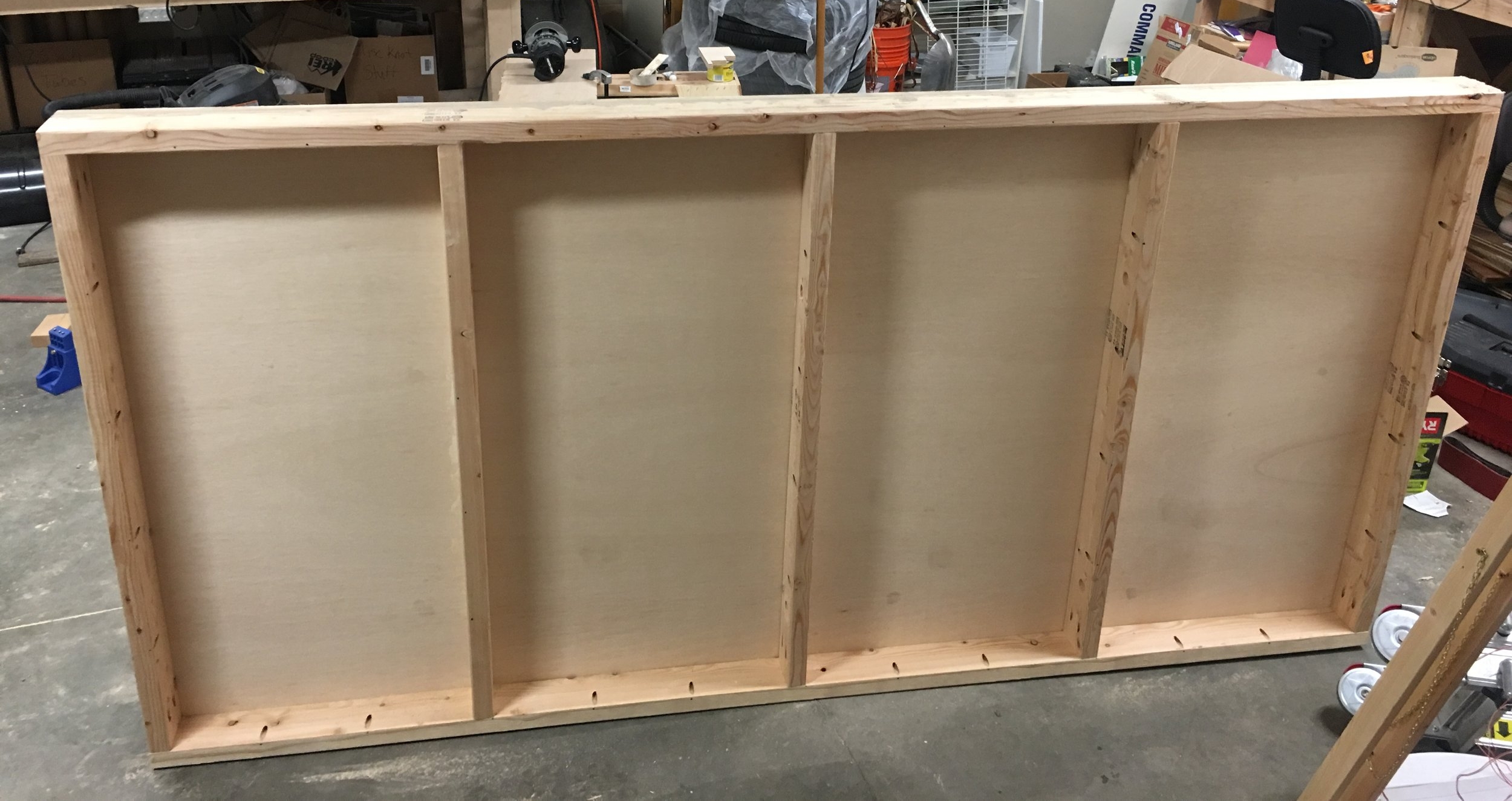
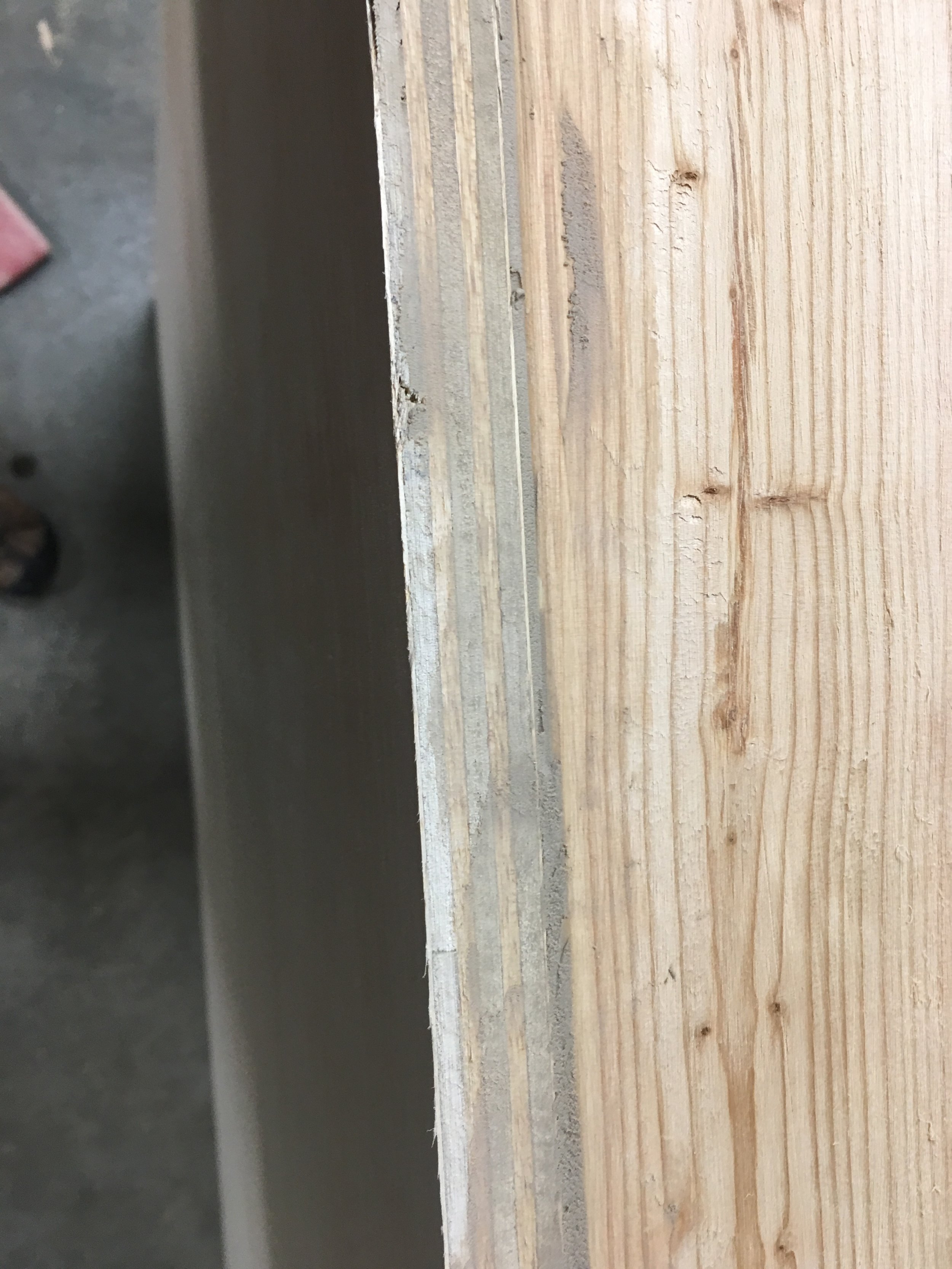
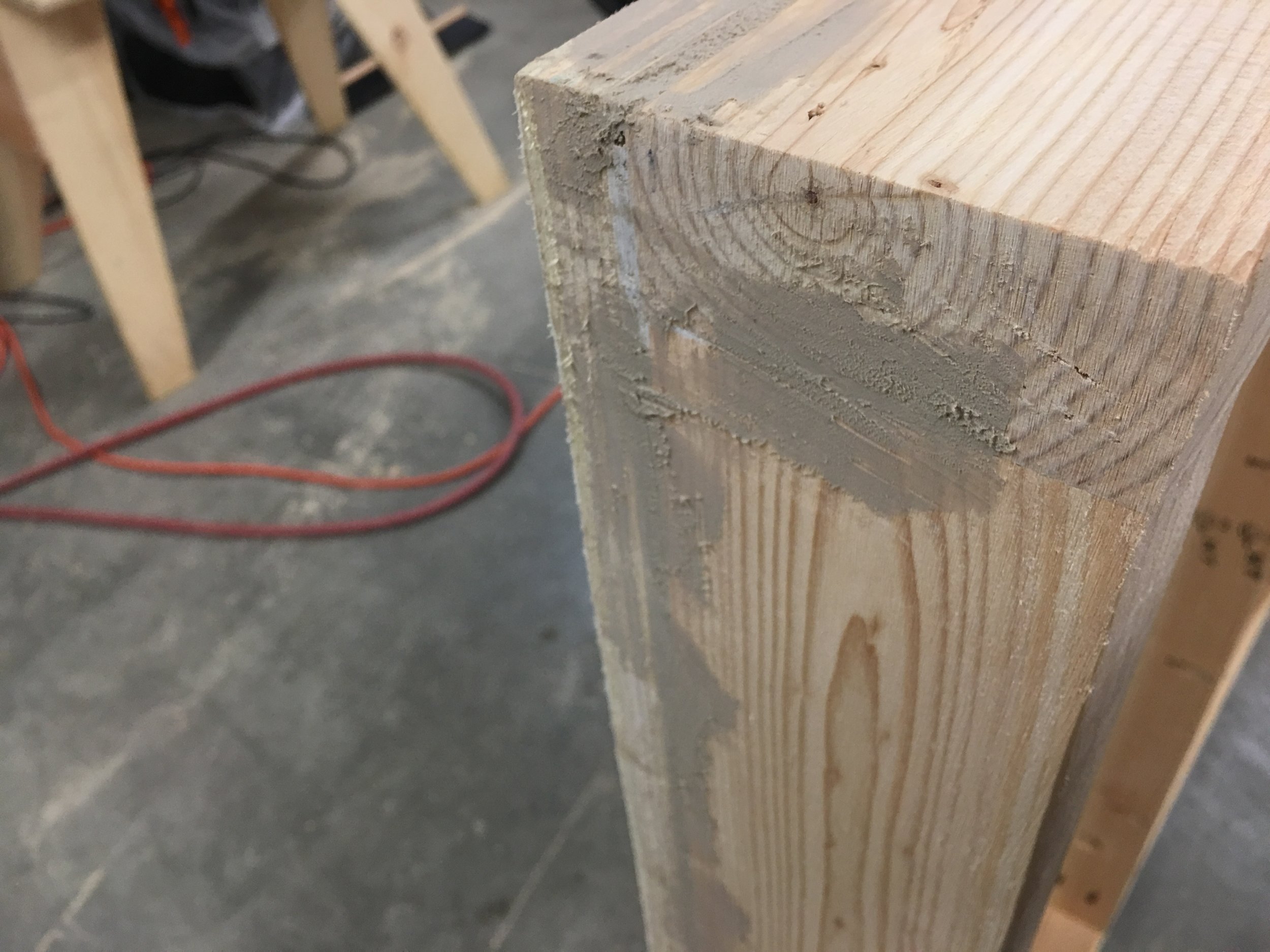
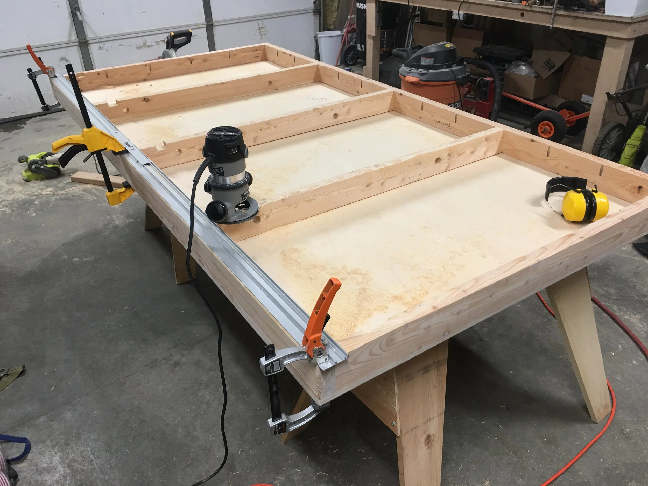
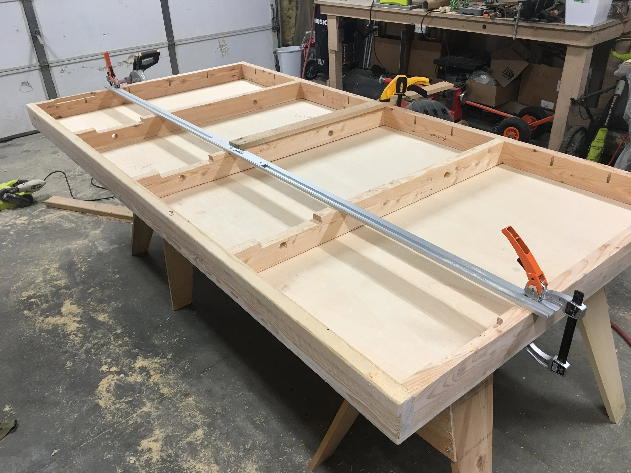
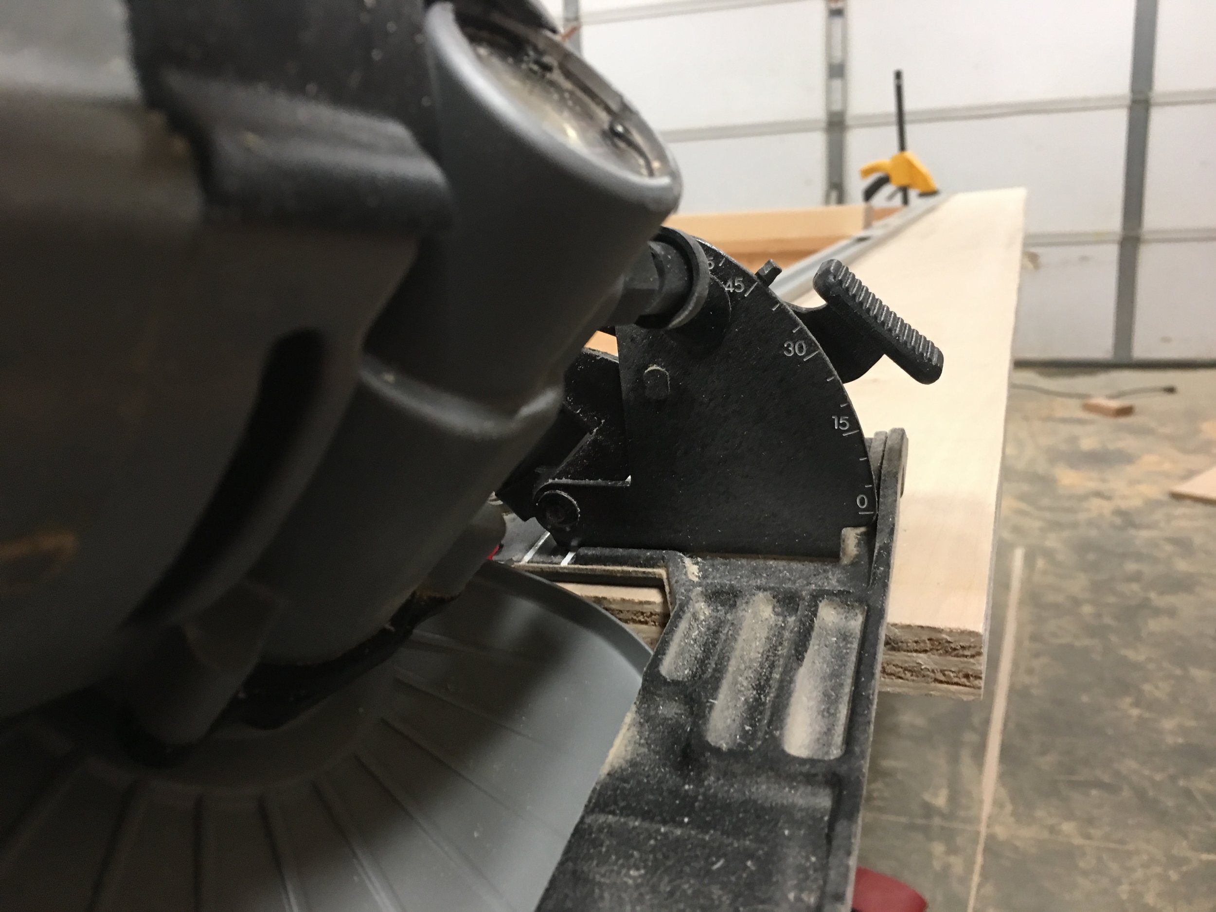
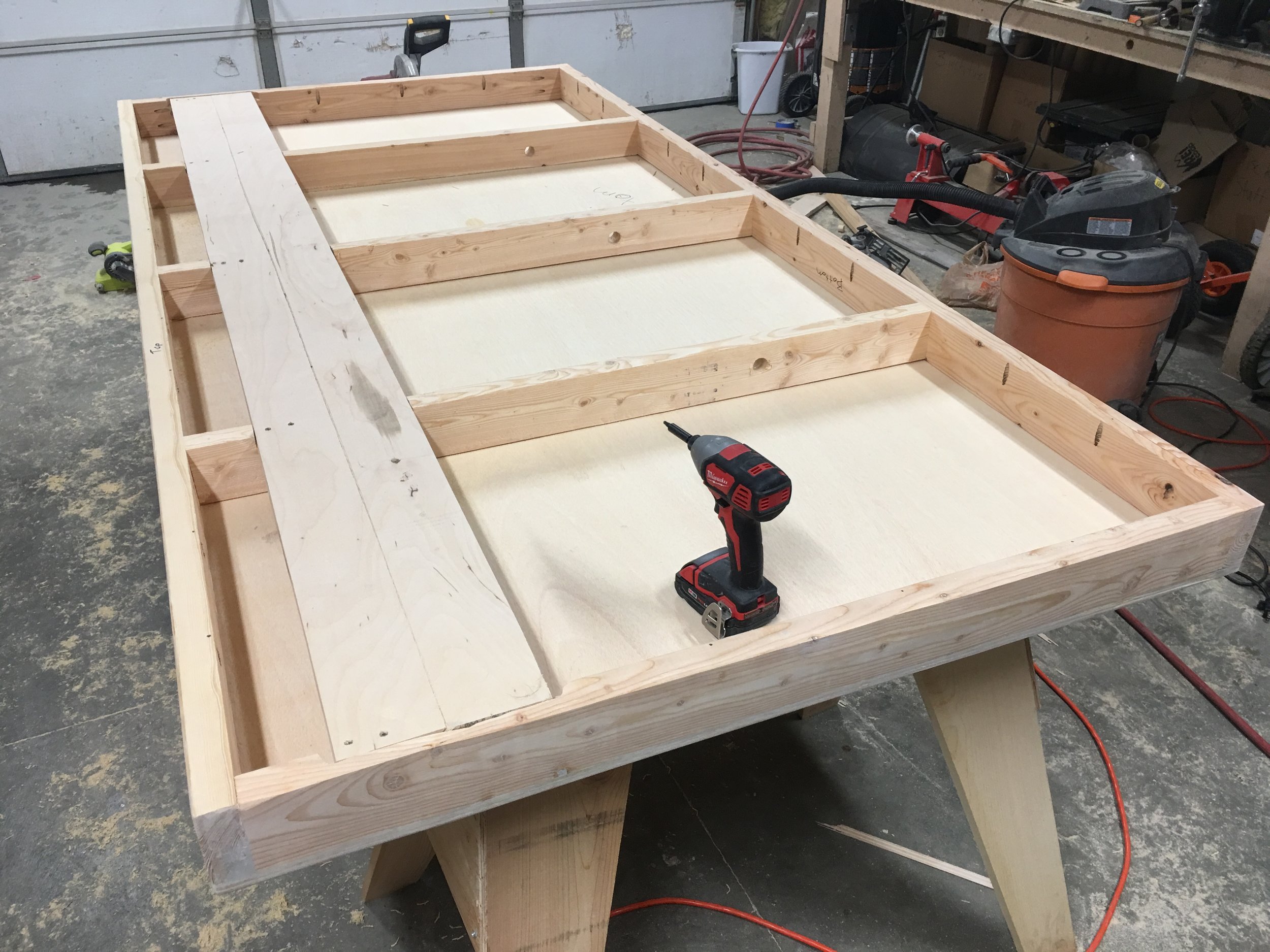
Each bug would be roughly a foot and a half in diameter so with 5-6 of them, a 4' x 8' sheet of plywood seemed like a good size to go with. I needed to be able to route wires to each of the signs and have room for some electronics, so I framed in the plywood with 2x4s. I used pocket holes to secure the plywood to the 2x4s so no fasteners would be seen from the front. Ideally, I would have used a jointer/planar to ensure all my boards were straight and were flush with the plywood, but I didn't have access to those tools. Instead, I just framed everything out the best I could with raw 2x4s, filled the gaps caused by the rounded 2x4 edges and imperfect framing with wood filler and sanded everything smooth.
The wall that the exhibit was going to be mounted on had some trees painted on it that we wanted to keep for the Bugs exhibit. Early on we tossed around the idea of going with something clear so we could see through to the trees. Instead, we decided on the plywood and we would just paint it the same color as the wall, mount it and then paint the trees on it so they matched up with the trees on the wall. This all needed to happen before I mounted the signs and electronics, so my next order of business was to figure out exactly how it was going to be mounted to the wall. A few well positioned fasteners was ok with the museum, but I wanted to make sure I could easily unmount the exhibit in case I needed to get to the electronics, so using several lag bolts through to studs wasn't appealing.
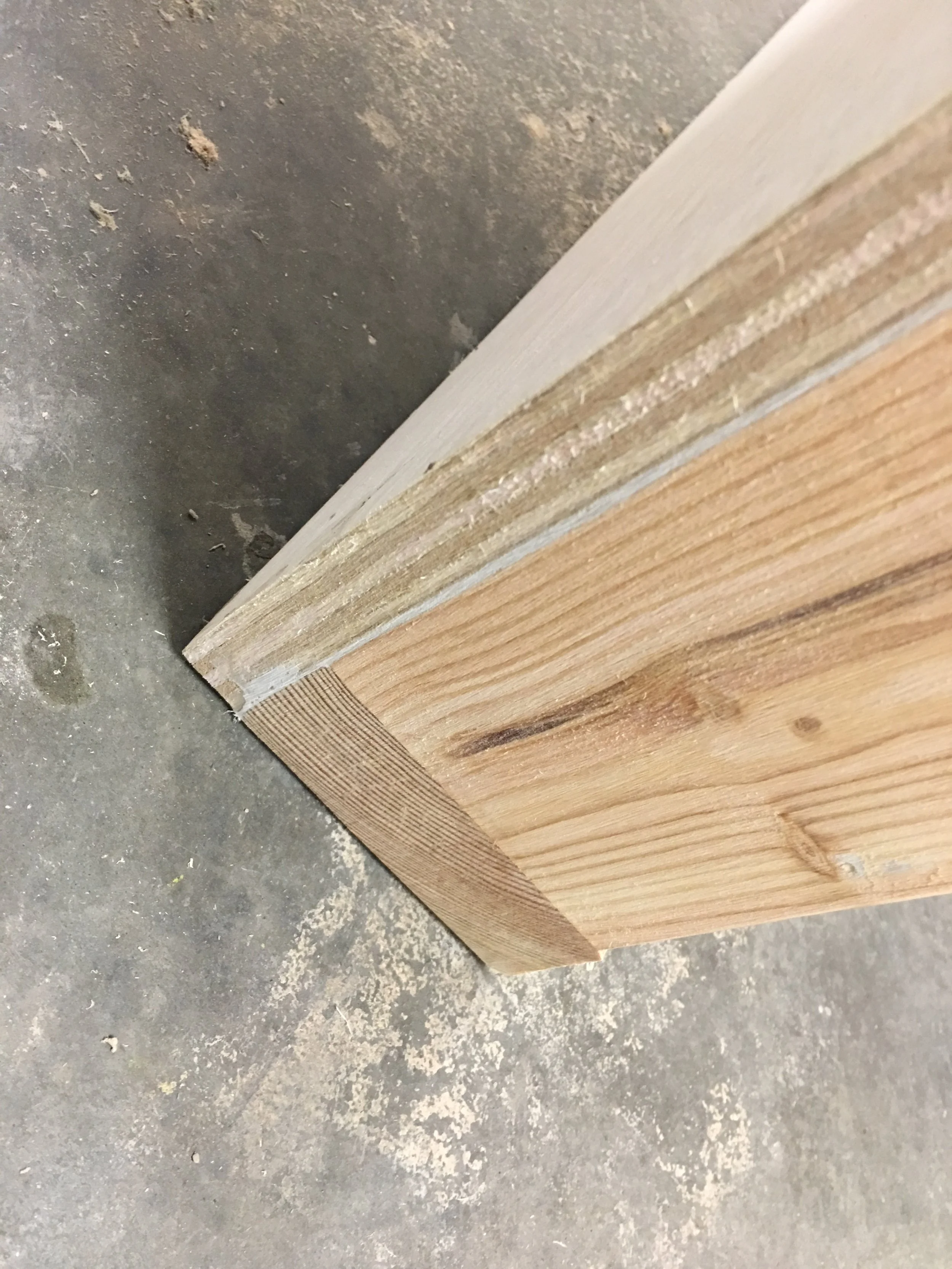
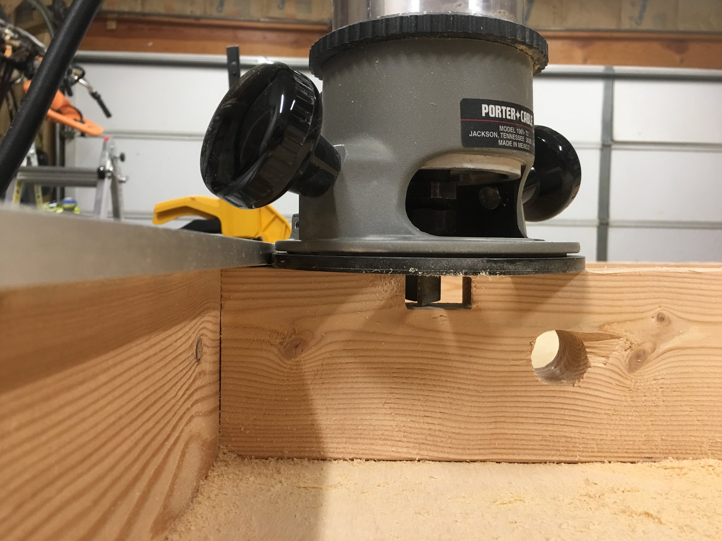
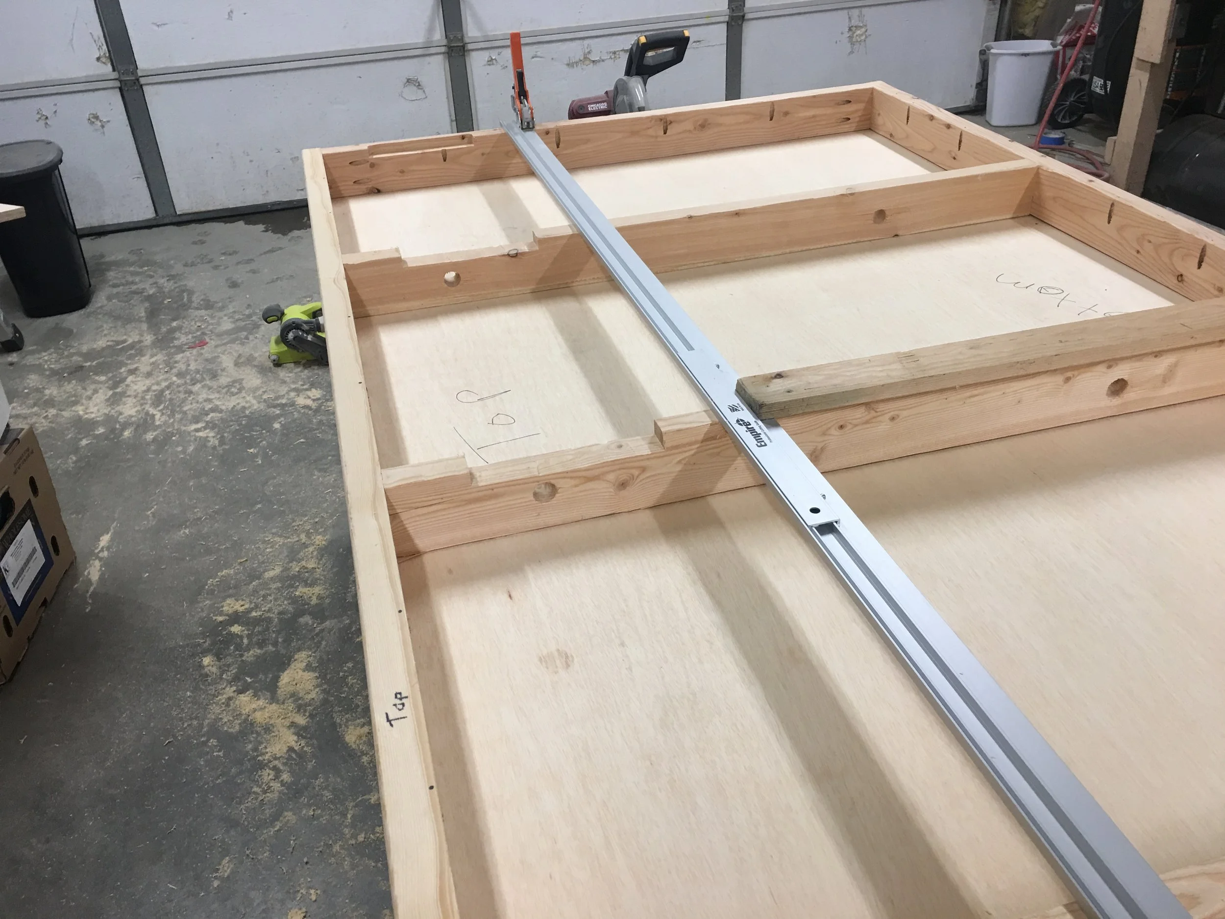
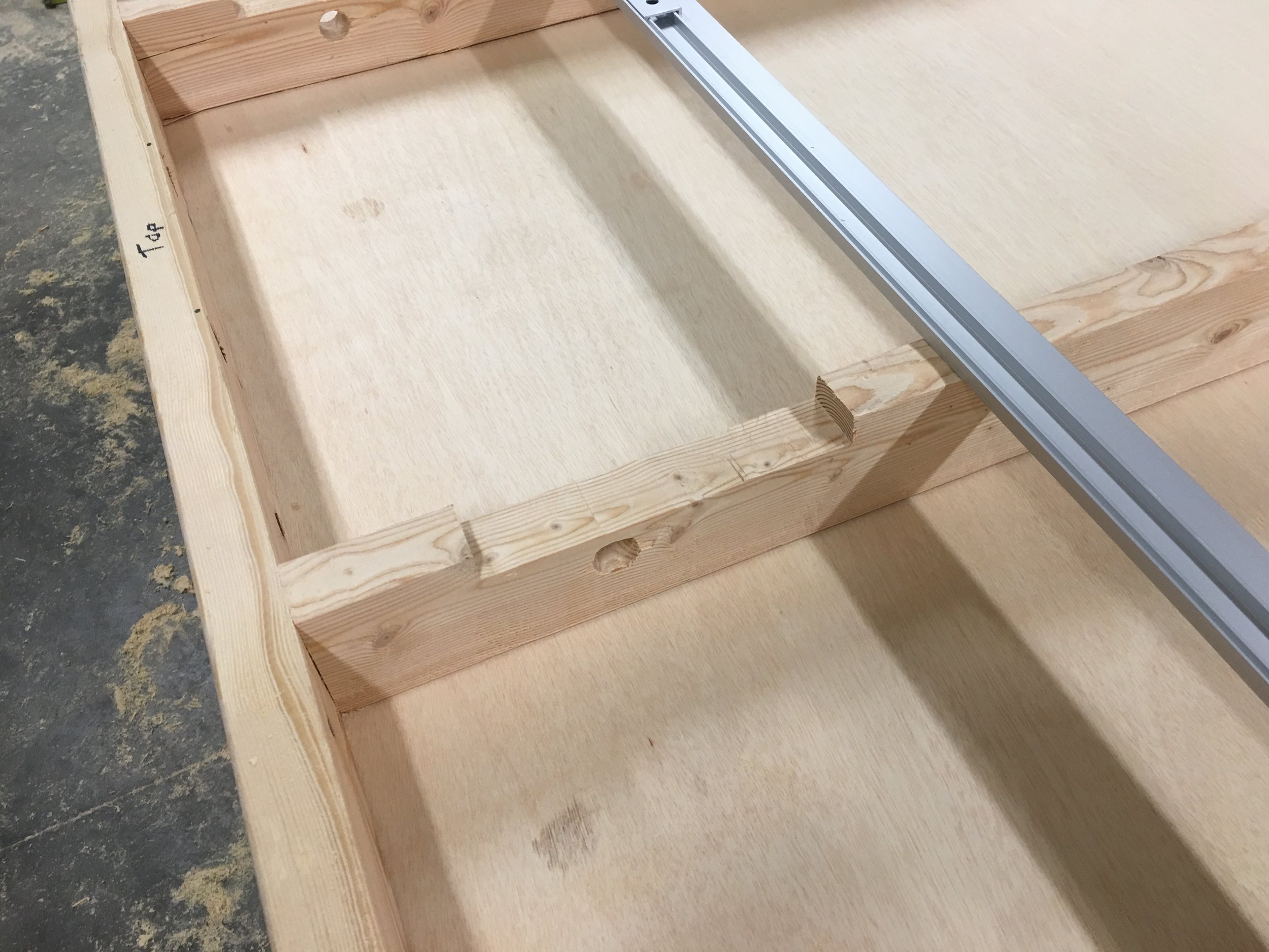
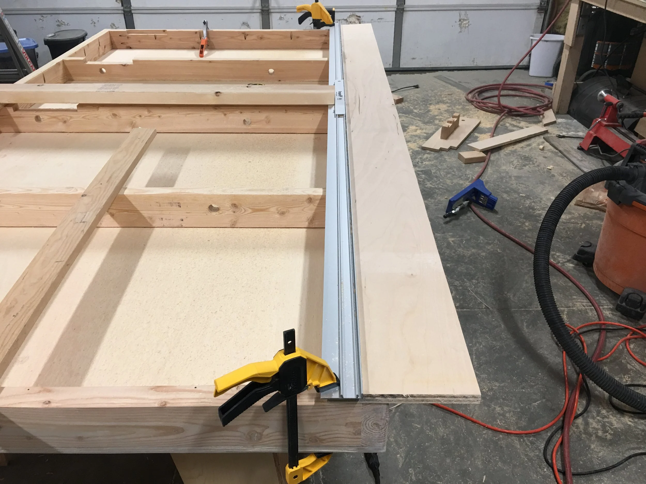
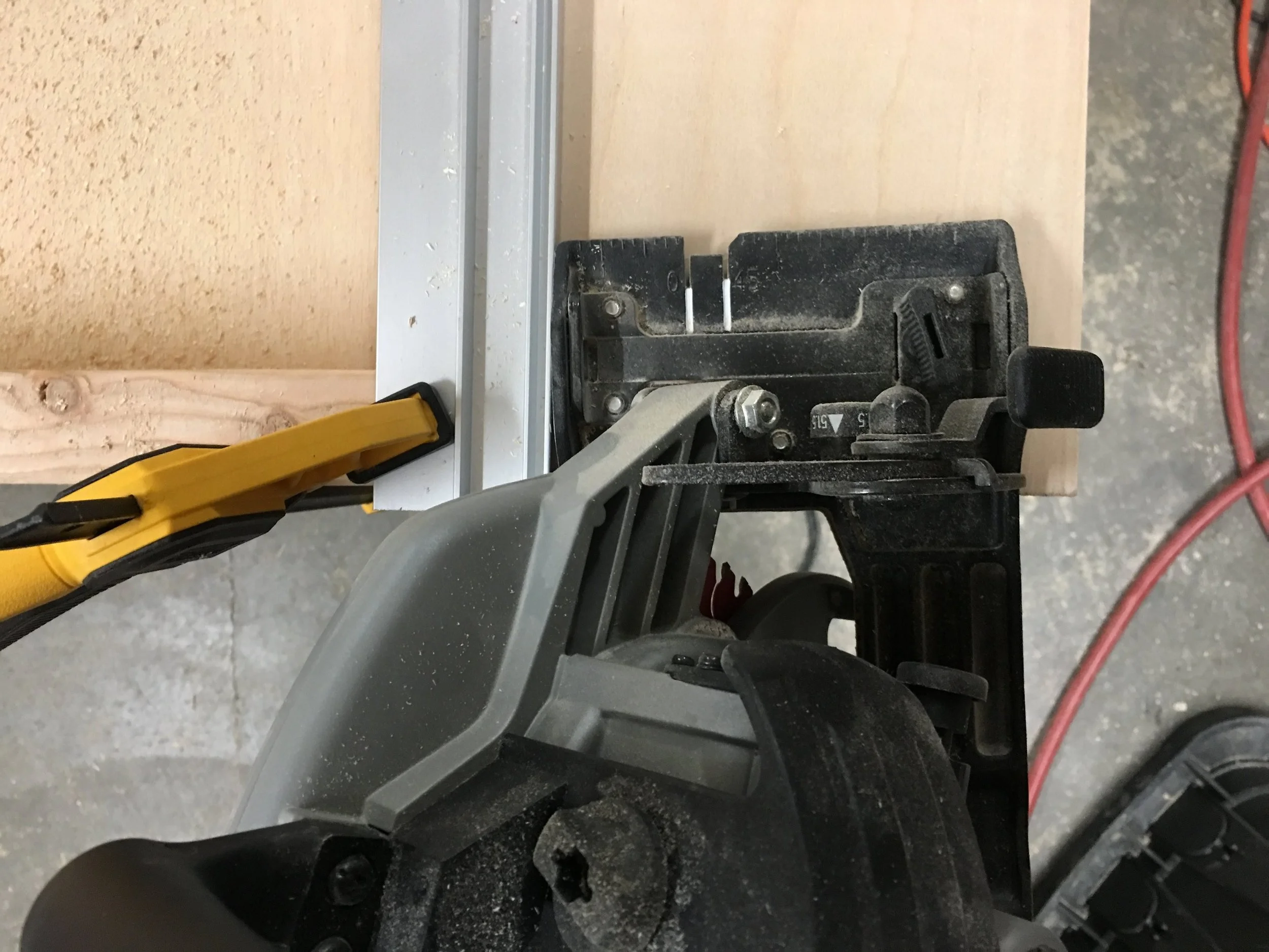
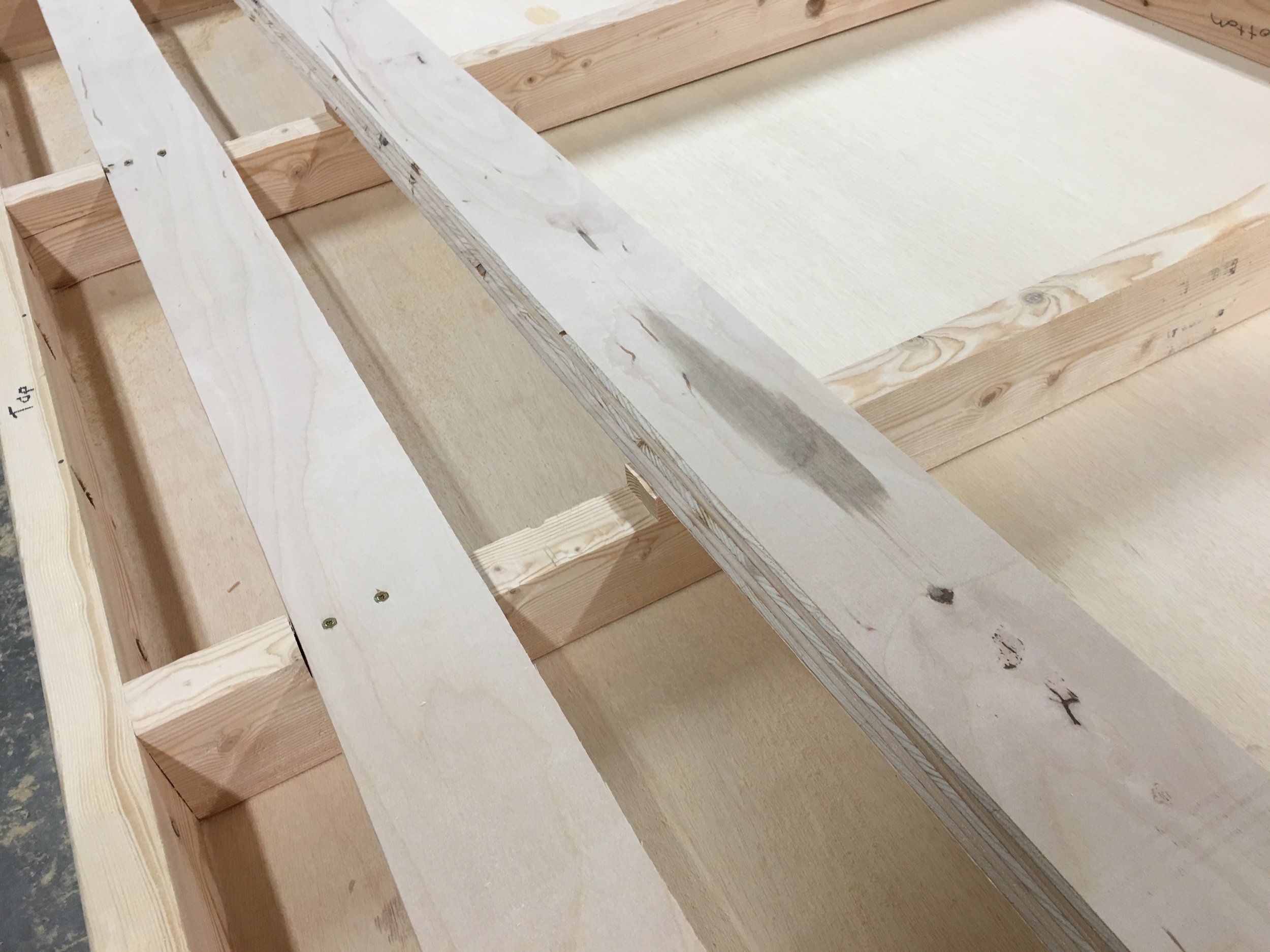
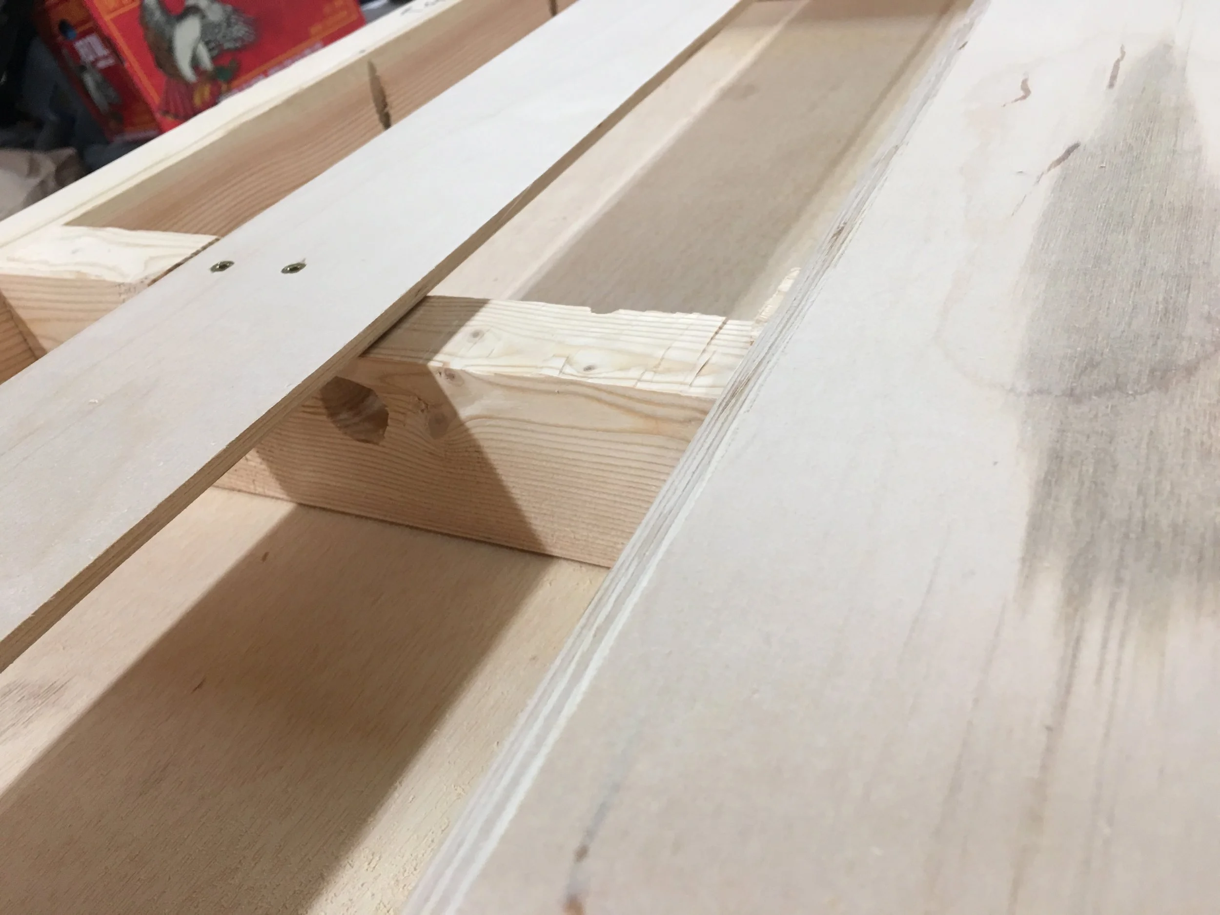
After some searching, I found what is called a French cleat. The idea is you take a piece of plywood the length of the object you're mounting and cut it in half lengthwise at a 45 degree angle. One piece is mounted to the wall and the other is mounted to the object you're mounting. The two plywood pieces fit together perfectly, so the object will seat nicely and securely to the cleat. The object being mounted can readily be removed from the cleat as well and a single screw through the bottom to a stud can keep it from being pulled off the wall. I had a spare 1' x 8' sheet of plywood left over from my standing workbench that was perfect for the job. I routed out sections of the 2x4 framing so the plywood would be flush when mounted, cut the plywood at a 45 and mounted one of them to the back.

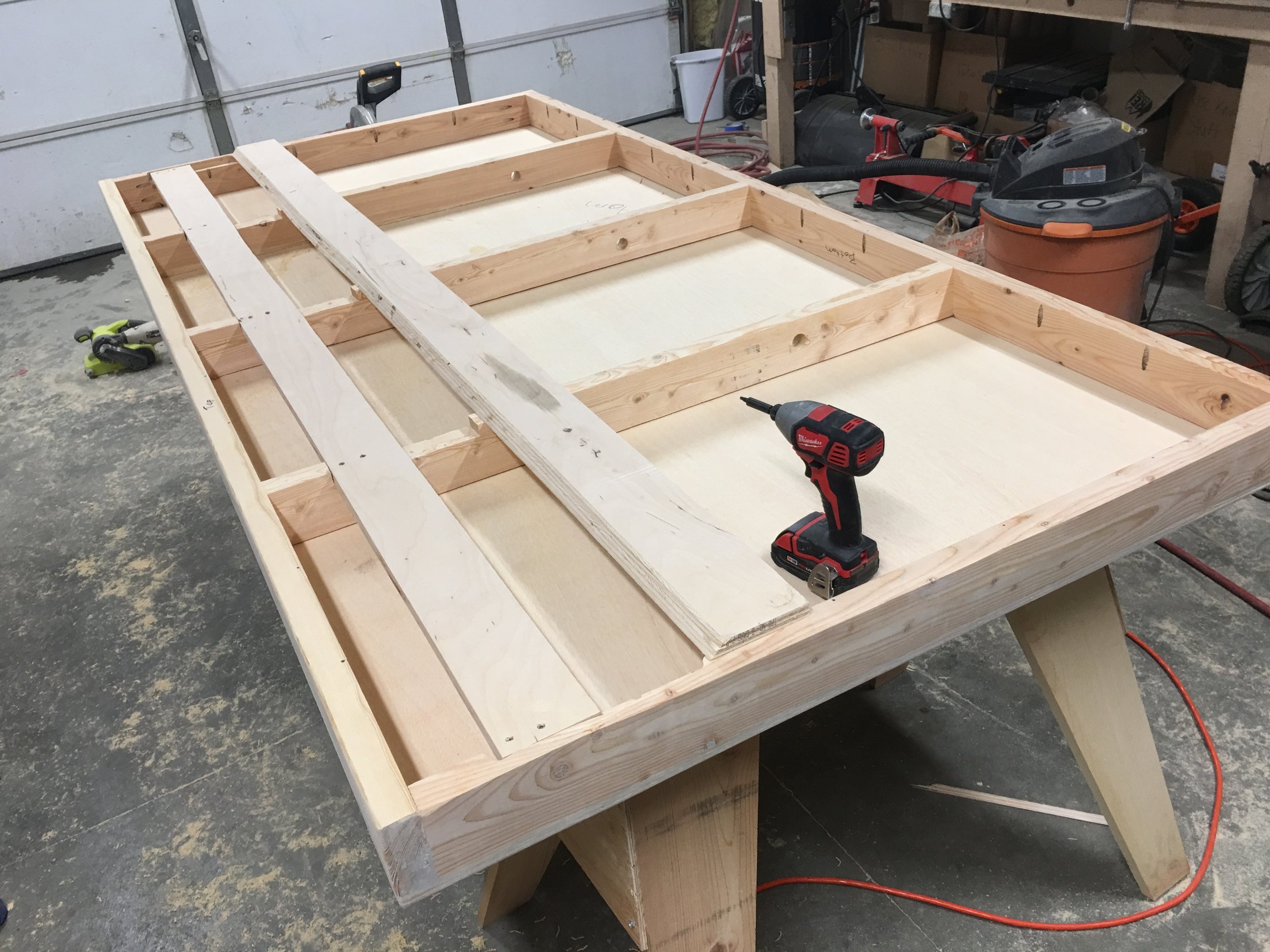
I dropped off the framed plywood at the museum. They painted it green and placed mockups of the trees and bugs on it.
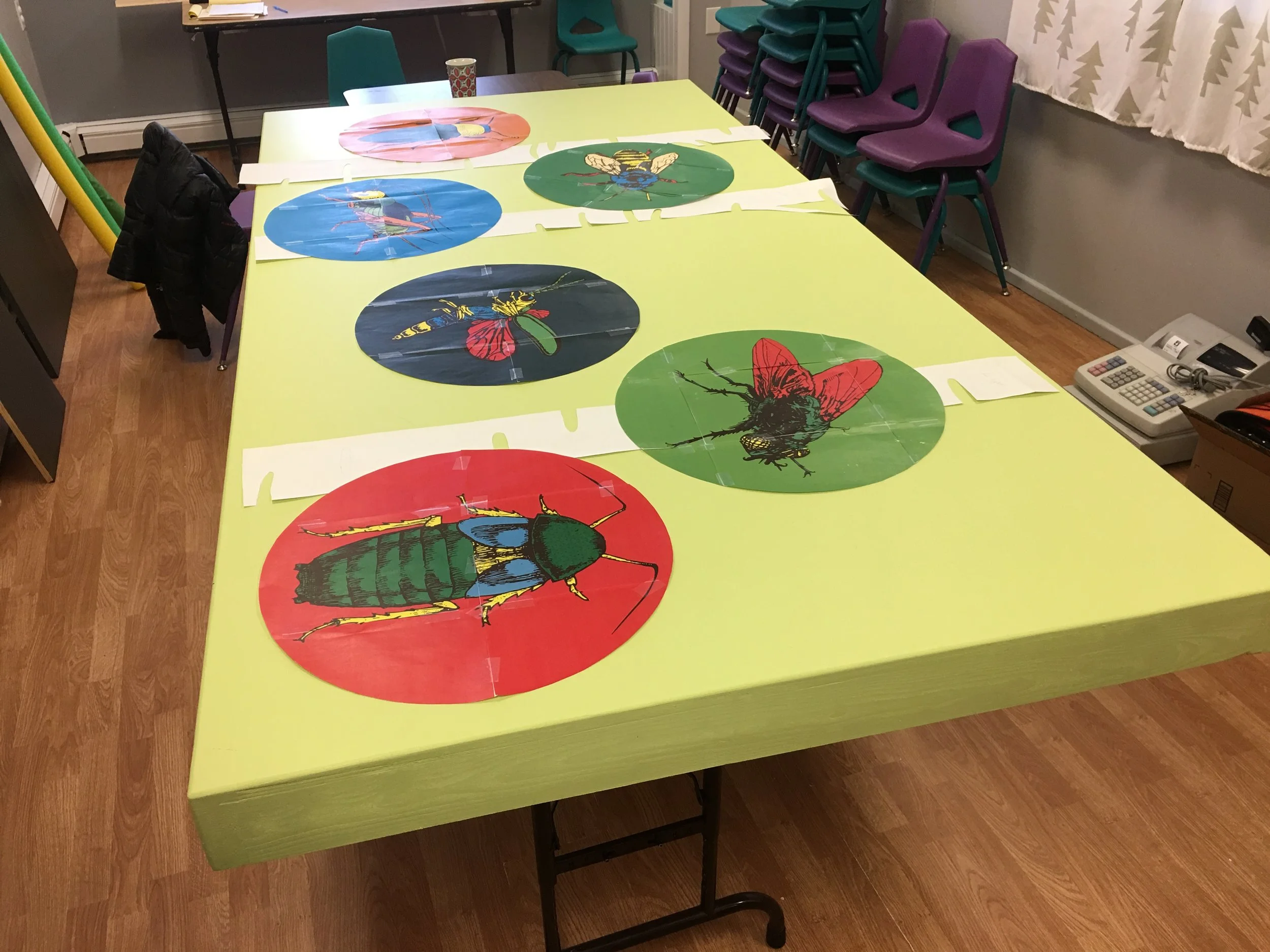
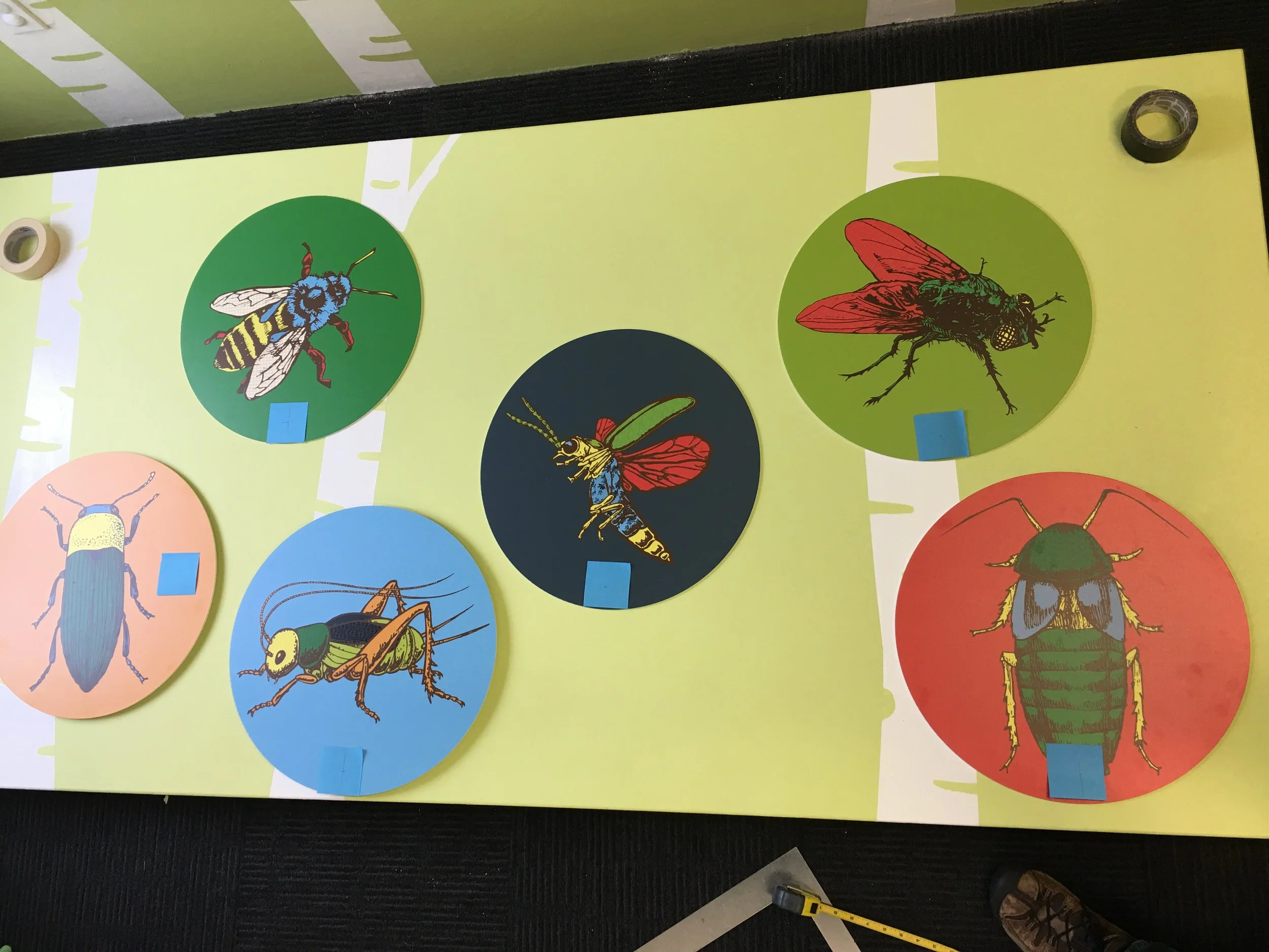
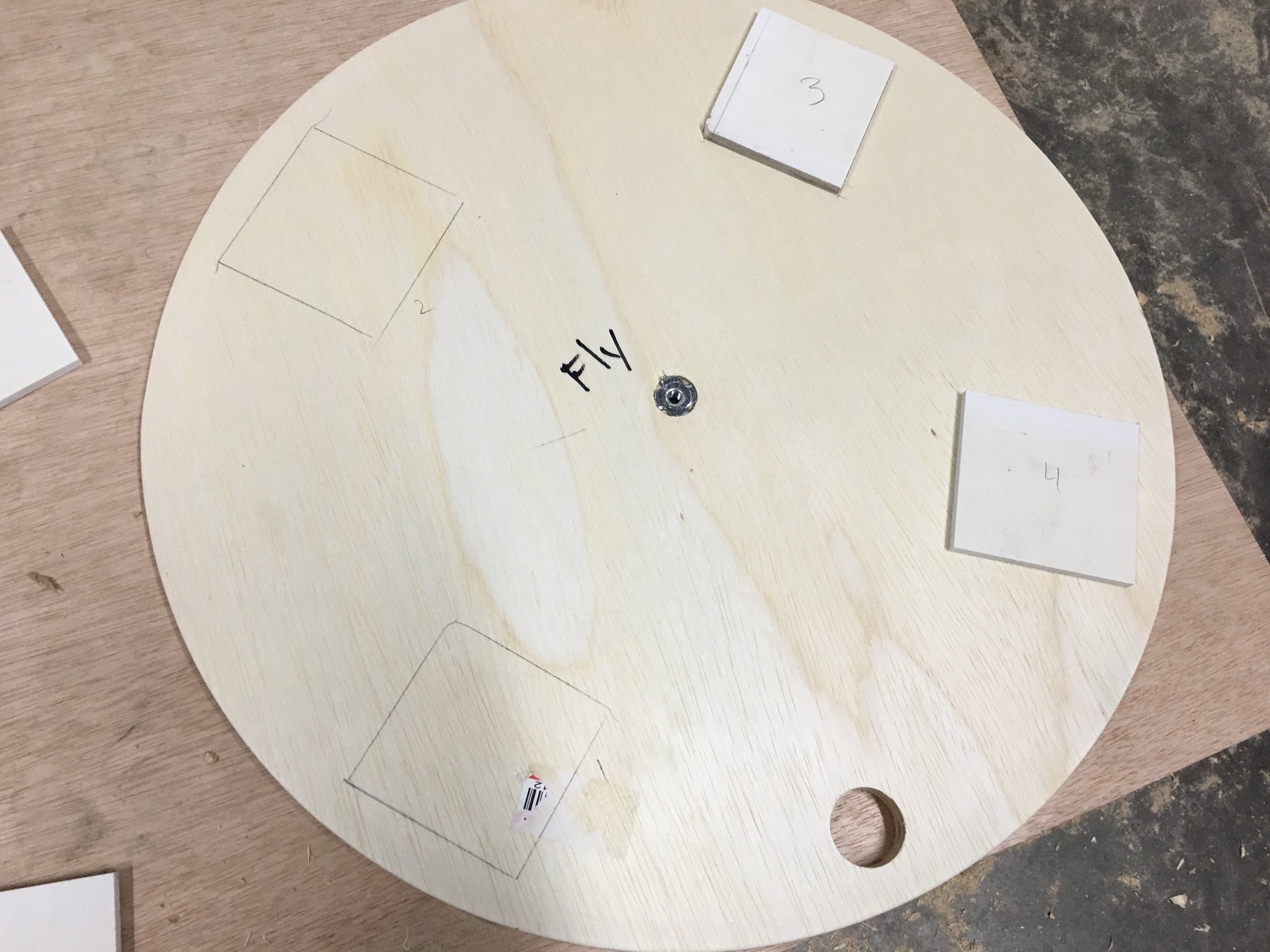
I came back to mount it to the wall so they could paint the trees on it. Then we unmounted it so we could lay it on the floor to rough out where the signs would be mounted to it. The museum had the signs printed on PVC by Allegra Marketing. We placed them where we wanted them to be mounted and used Post Its to mark where the buttons would go (or the handle for the click beetle). We used rolls of tape to rough out where the speakers would go. I planned to mount the click beetle on 1/2" plywood so it could be mounted to a Lazy Susan, so I brought a couple scrap pieces to see if we wanted to mount all the signs on plywood. You can see the cricket and click beetle are raised a bit. We decided all the signs should be mounted on 1/2" plywood that attached to the main board.
I brought everything back to my garage so I could finish the rest of it. To cut the plywood circles I mounted my router to a board and drilled a 1/4" hole 9" away from the bit, so the board could spin on a 1/4" machine bolt, giving me an 18" circle. I used T nuts in the 1/2" plywood so that I could mount and unmount the signs from the back of the exhibit without any hardware showing. The same T nut was used to mount the router board so I could cut the circle.
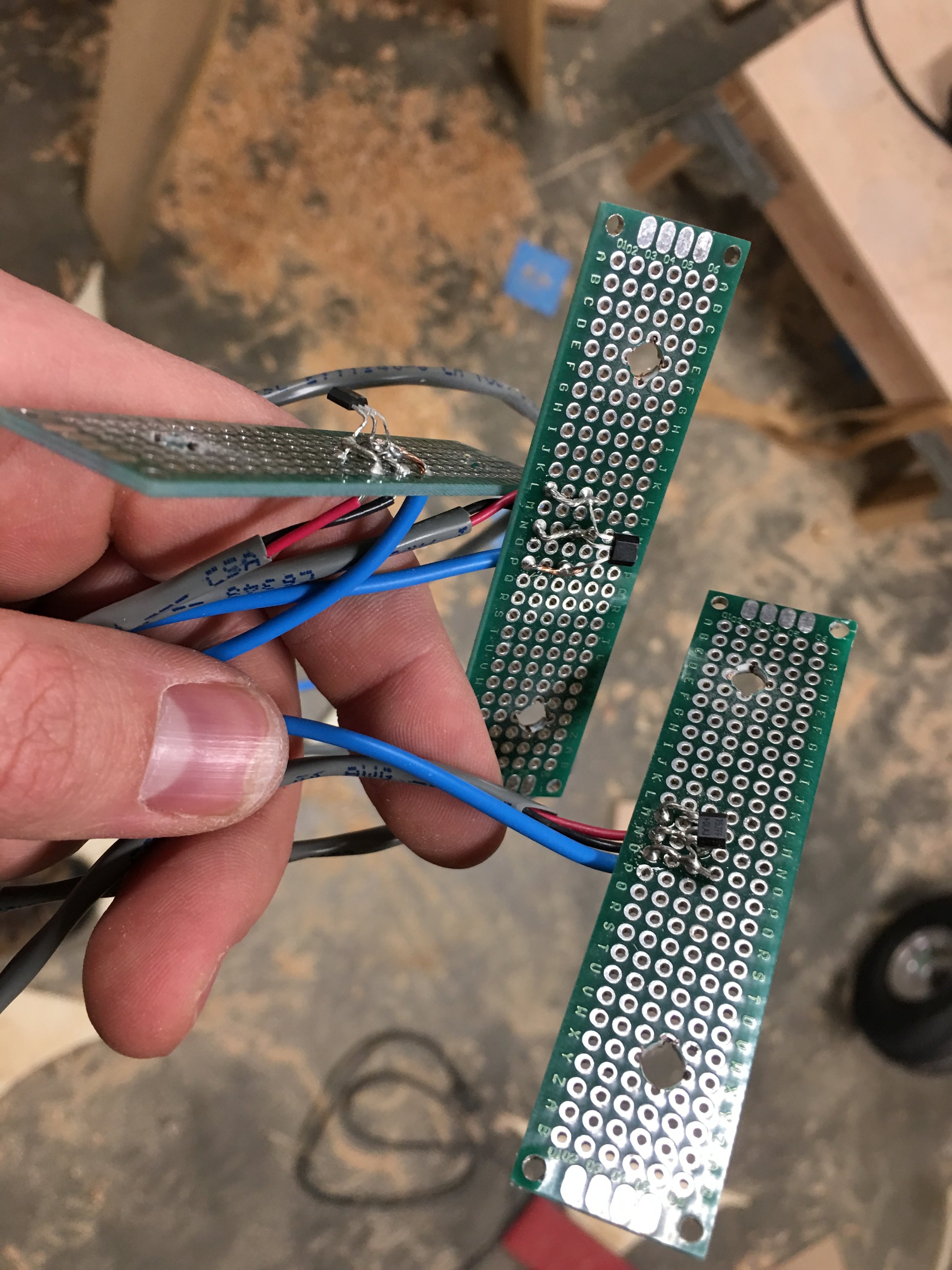
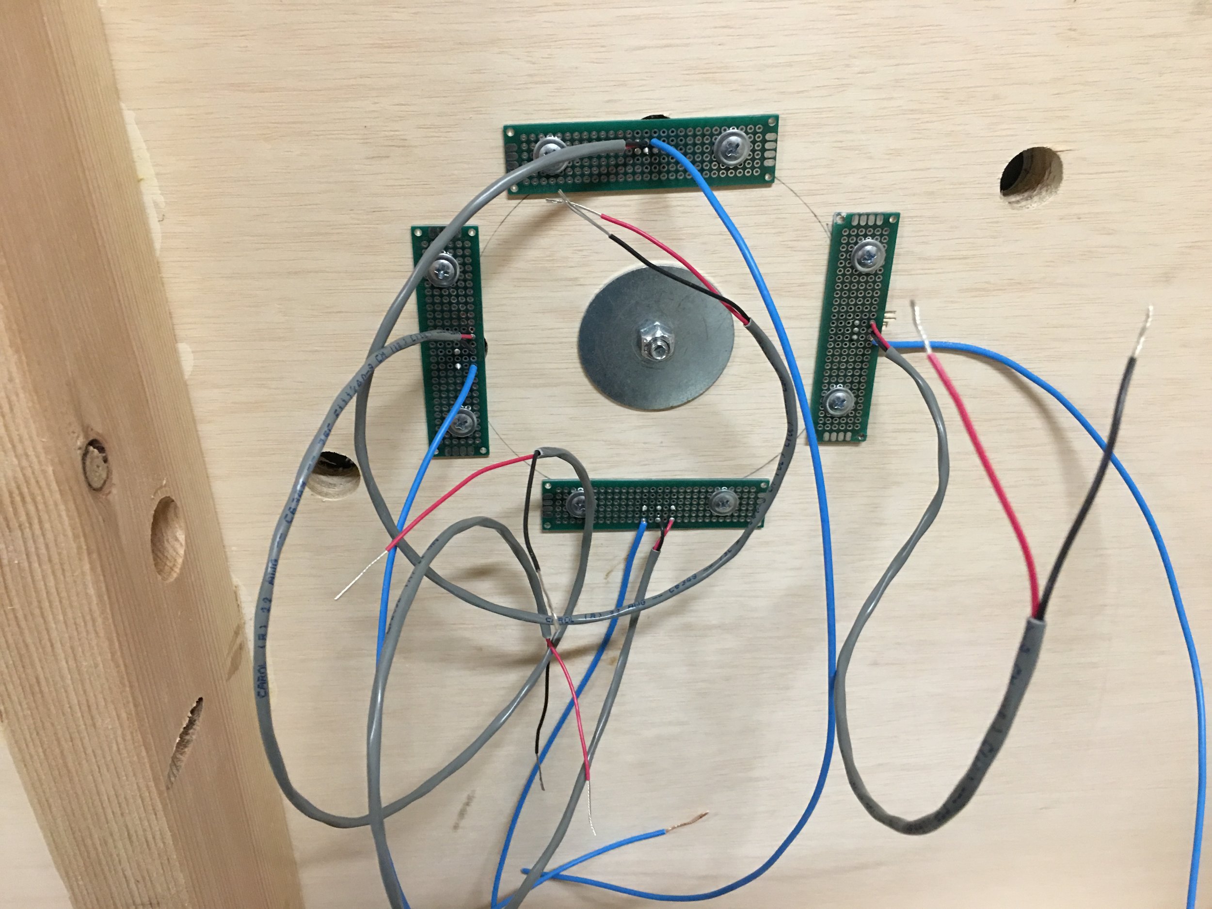
Next, I had to figure out how to trigger the click beetle sound. I could have gone with a switch (or multiple) that would be triggered by a rotating arm of some kind, but I figured hall sensors would be more reliable. A hall sensor behaves like a switch that is triggered by bringing a magnet within range. I soldered some hall sensors to some protoboards so I could easily mount them on the back and then mounted a magnet to the back of the 1/2" plywood that the click beetle was going to be mounted to. The 1/2" plywood would then be mounted with a 1/4" bolt to the 3/4" plywood with a Lazy Susan for some extra support.

The firefly was another tricky part of the project because I suggested we cut out the tail portions, replace them with frosted acrylic and light them up with some RGB LEDs. The firefly was designed as a vector graphic, so we had everything we needed to use a laser cutter to get a precise cut. Alignment in a laser cutter can be tricky, though, especially when the firefly sign is bigger than the bed of the laser cutter. There was a removable front panel, though, that allowed the sign to fit in the laser cutter. With the sign in the laser cutter, I was able to guess roughly where my design would need to be for the laser to cut it out. On the computer I positioned the design in roughly the same place, then cut the design on a scrap piece of MDF that I could reliably align to the top and left edges of the laser cutter. Then I put the sign in the laser cutter and aligned it exactly with the scrap piece of MDF. I put some masking tape on the firefly and used very slow, low powered settings to prevent any scorch marks from getting on the sign. The cut was perfect!
I later read that cutting PVC with a laser can put off some nasty fumes (Chlorine gas) that can damage your laser and your health, so this may not have been the best idea. Certainly don't do a significant amount of laser cutting with PVC. If you do go for it, limit how much you cut and make sure you're in a well ventilated area with a blower going to exhaust all the fumes from the laser cutter outside. I won't attempt this again, now that I'm aware of the dangers, but here is the sign being cut.
Here is an early experiment with programming the flash patterns using an LED strip.
I ultimately went with an 8x8 LED grid that filled the space better and could give a more organic feel and mounted it behind the sign. You can see how I smudged the sign by letting glue seep out onto the front. I was so bummed and was prepared to do it again, but we decided the sign was probably going to get beat up soon anyway.
The LED grid is controlled using an Arduino compatible board called the Pololu A-Star Mini LV 32U4 (comparable to the Arduino Micro). The Arduino listens for messages over serial which triggers random flash patterns. The organic glowing and fading of the LEDs is done using a library called FastLED which has some great Perlin noise functions.
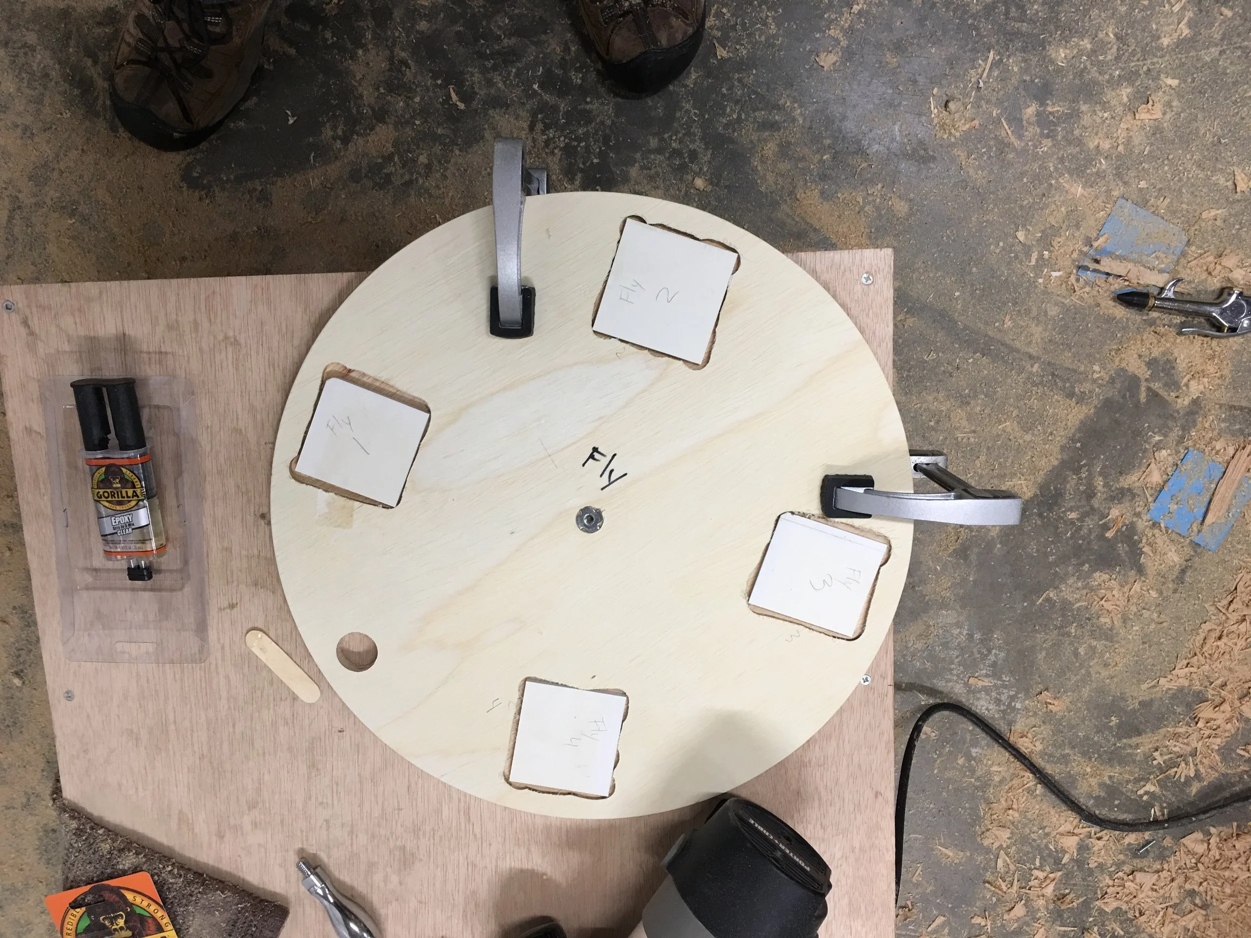
Another tricky piece of the exhibit was figuring out how to properly attach the PVC signs to wood. We didn't want any fasteners showing, so glue was the only option. I didn't have any experience gluing PVC to wood. Epoxy seemed like the best option, but there was a lot of surface area to cover so it would be expensive. There were some construction adhesives that seemed like they had potential, but I had an old PVC sign laying around in my garage and some PVC glue for plumbing as well. I knew that PVC bonds were stronger than the PVC, so I cut up the sign into 24 pieces so I'd have 4 for each bug sign. I routed out room for each piece and used some epoxy and screws to fasten them to each 1/2" plywood circle. Then I used PVC glue on each piece and some E6000 glue everywhere else before clamping the bug signs to the plywood circles. The T-nut also allows the sign to be easily mounted and removed using a single 1/4" bolt. We'll see how they hold up!
The brain of the exhibit is a Raspberry Pi B+ (the STEAMlab has a bunch of them lying around). Attached to the Pi is a HiFi Berry Amp 2, which is a class D amplifier for providing up to 60W of power to 4-8Ohm speakers. I've used the built in audio out jack before to an external amp and wasn't happy with the quality. The HiFi Berry Amp 2 sounds great and has plenty of power to make sure everyone can hear it. I found some 4" white speakers on Amazon. I cut the holes for them using a 3-5/8" hole saw. To wire up all the buttons and hall sensors to the Pi, I used a Pi-EzConnect breakout board with screw terminals. The Arduino that controls the LEDs is connected to the Pi using USB, which allows for the possibility of code updates if necessary and easy communication over a serial port to drive the LEDs. I added an Ethernet port that is accessible on the side of the exhibit that can be used to ssh to the Pi and make any needed changes (volume adjustments, timing, sound file changes, etc.). All the code is up on GitHub.
Here's the final product! Go check it out at the Children's Museum of Bozeman STEAMlab.