

I've made knots in many forms. My software is able to generate instructions for tying them by hand, 3D models for 3D printing them, and tool paths for CNCing them. Most recently, I adapted my software to generate a combination of 3D models and instructions for assembling knots out of dowels and connectors. The idea was to create a kind of puzzle that would be challenging to assemble and could be an ornament or art piece when completed. Below is my first test run of the idea with 1/4" wooden dowels and 3D printed connectors. You can download all the 3D models and instructions for making your own below.
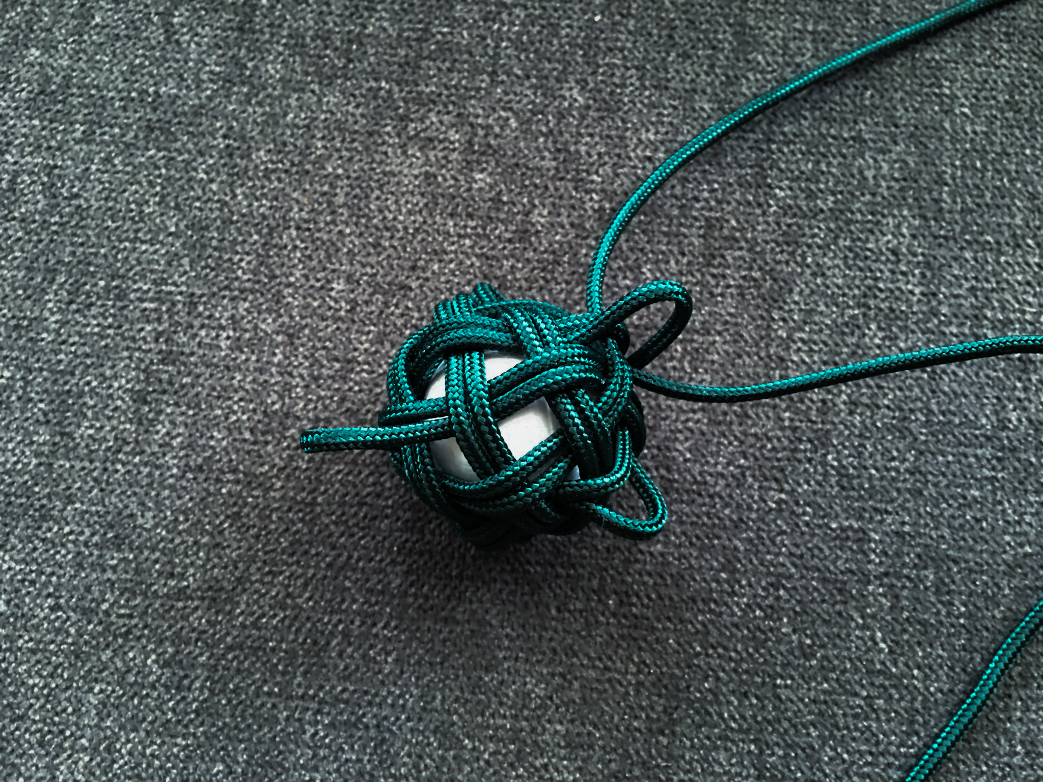
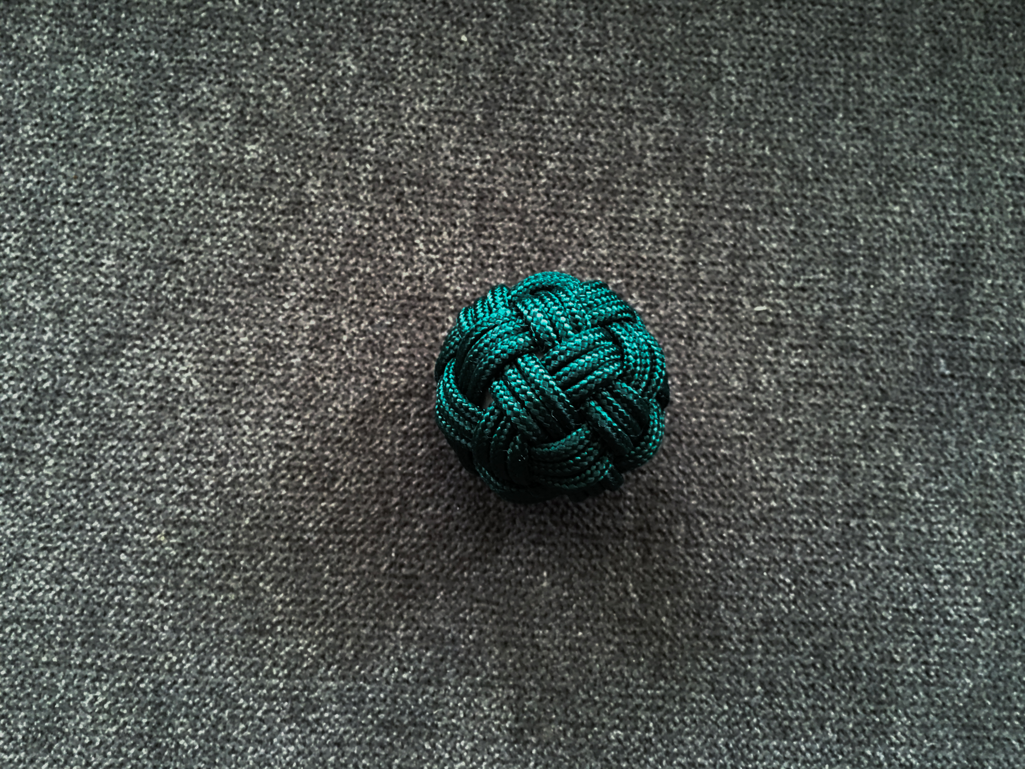
First, here's a little background. My favorite knots are globe knots that can be tied to completely cover a spherical core with a single strand. Here's a globe knot with 30 crossings that covers a 1" diameter foam ball. You can learn how to tie one yourself in this post.
With 3D printing, a globe knot can be made without a core and can even have a more open weave to emphasize that fact. My software can weave knots in 3D with all sorts of options to adjust how it looks. Here are some of my globe knot designs:

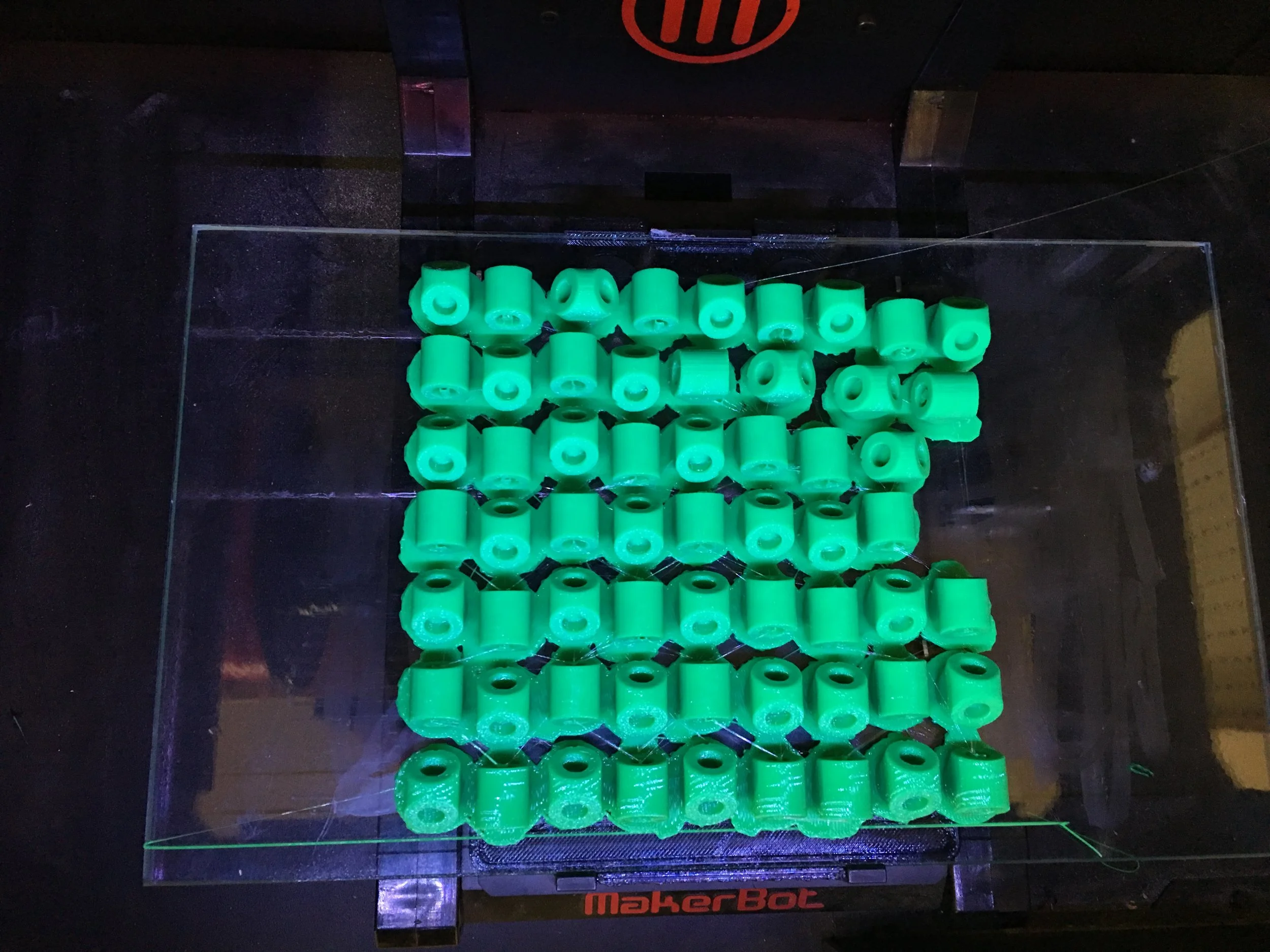
3D printing is very cost prohibitive when making larger objects, though, and limited in the size you can even make. I wanted to create one of these globe knots that was as big as my head, or even larger. I thought about how I could adapt my software to create bigger versions. If I forced the knots to use straight edges, I could use dowels and connectors could be made at the necessary angles to attach them. A big enough knot would still look like a globe even when using straight edges. I decided to start with a 30 facet globe knot, that is, one with 30 crossings or 60 connectors and 60 dowels (the same one that I tied above). 3D printing is the easiest way to create the connectors initially, but I'd like to eventually CNC them out of wood as well.
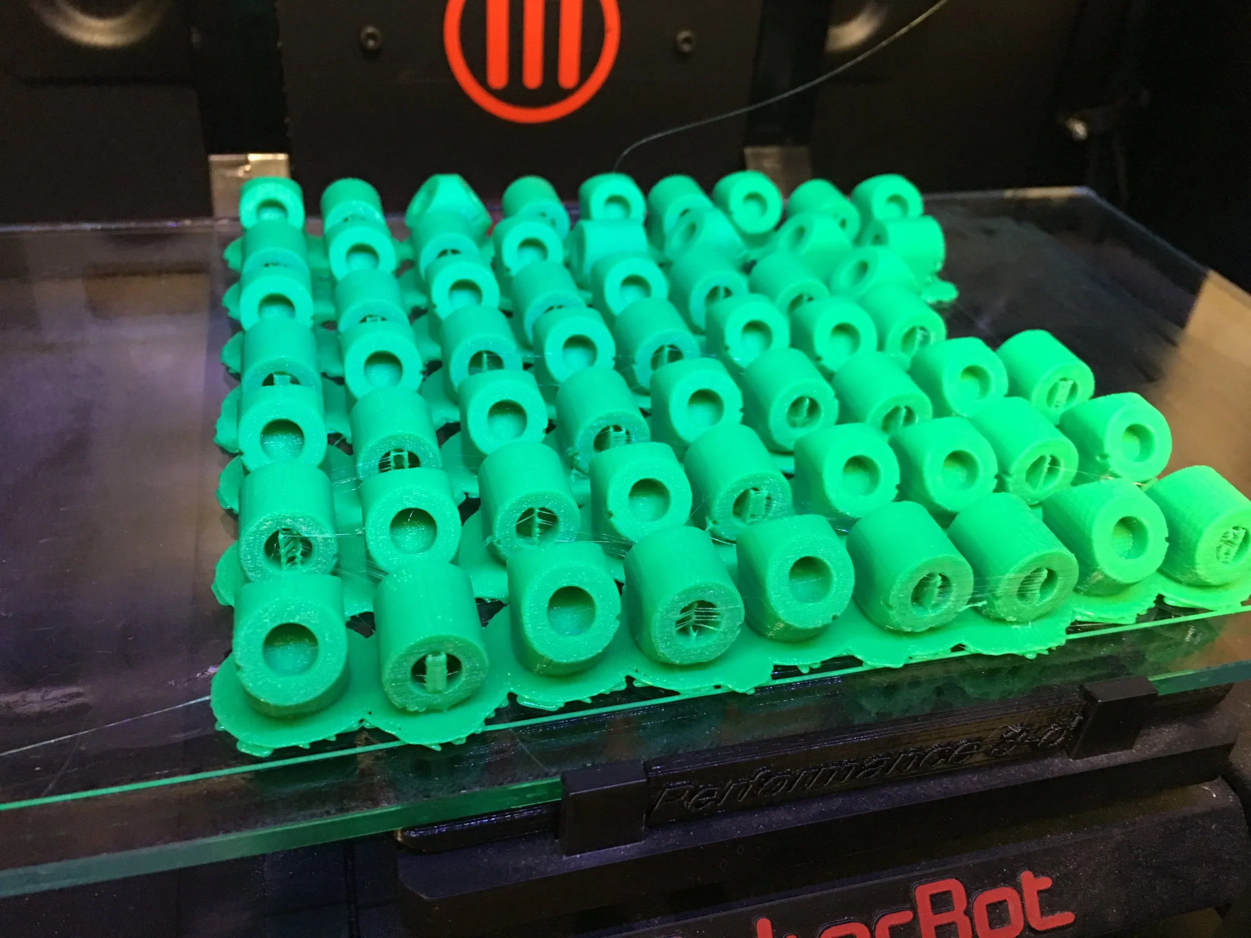
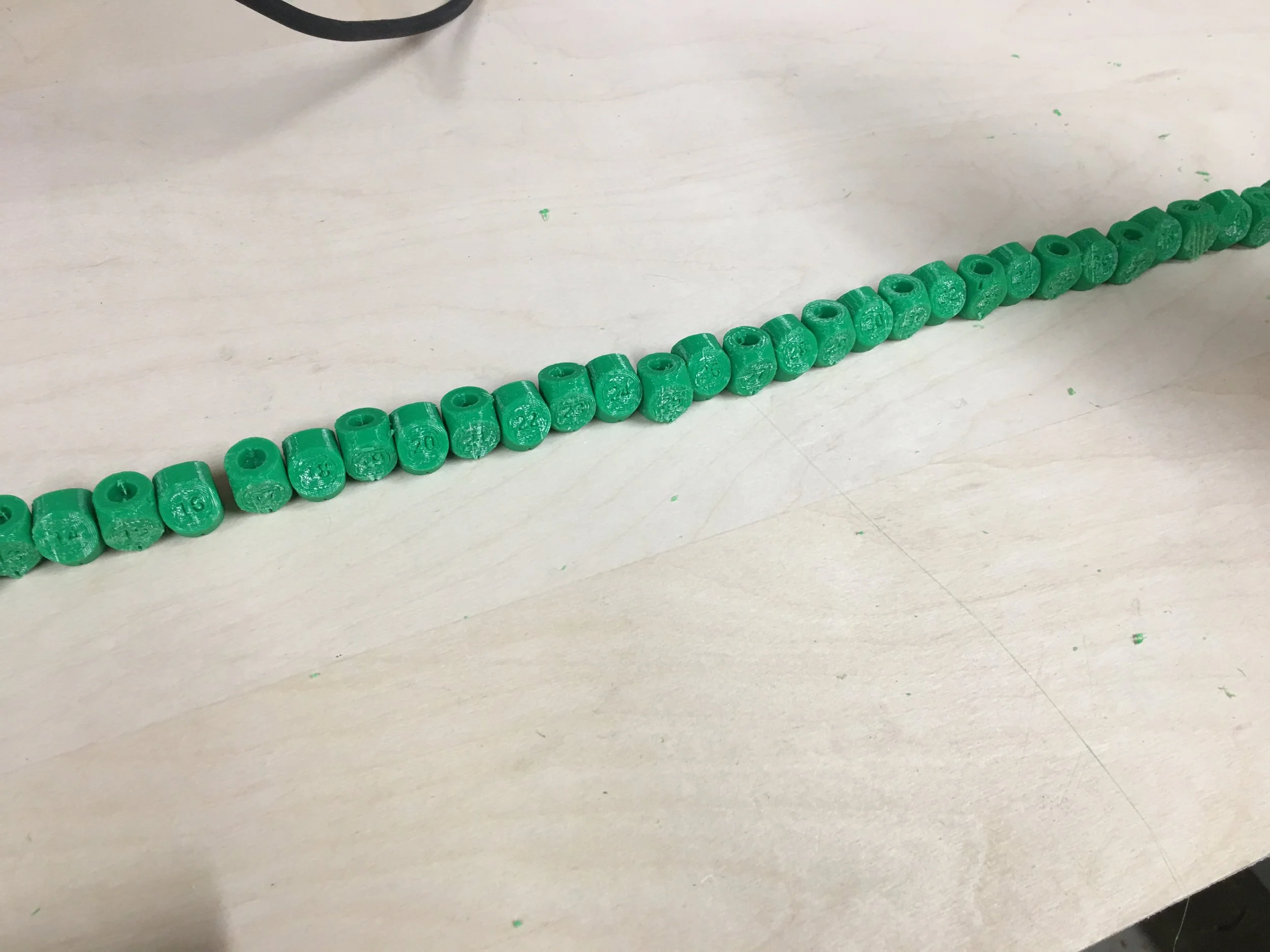
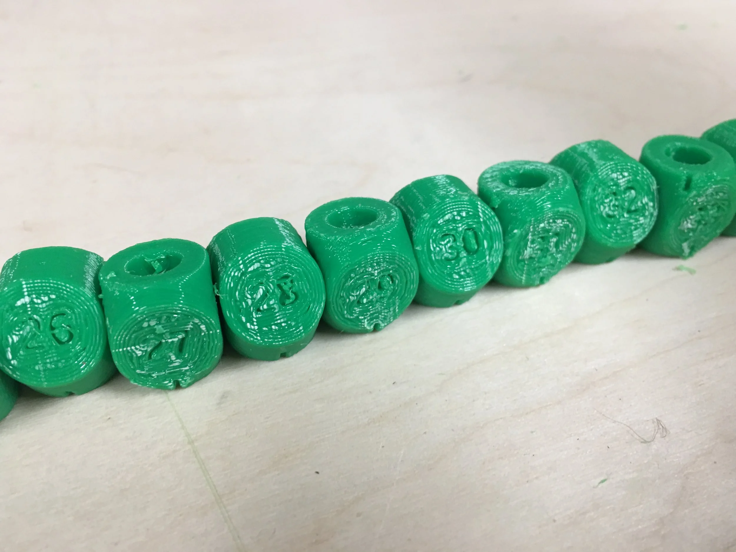
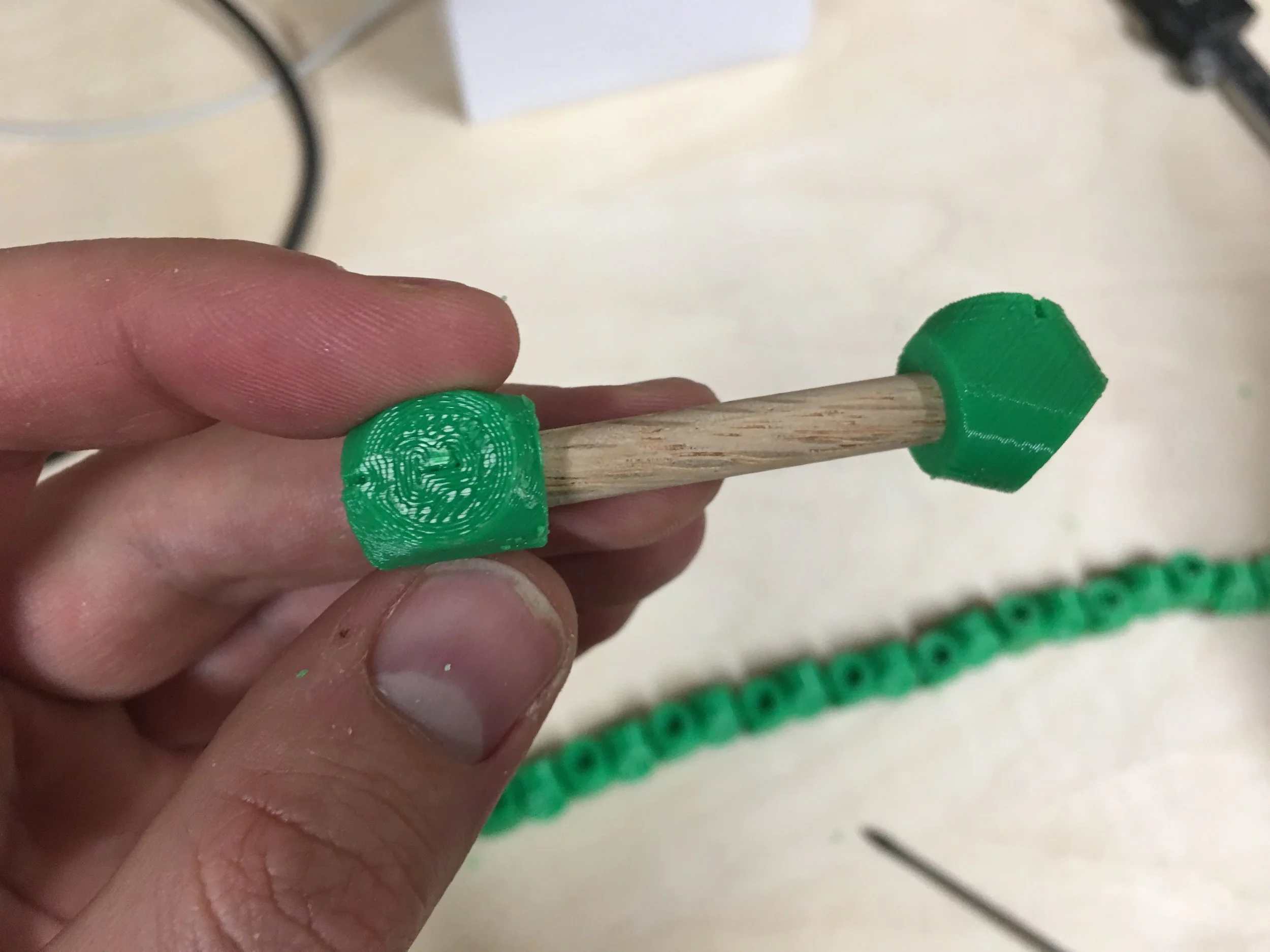
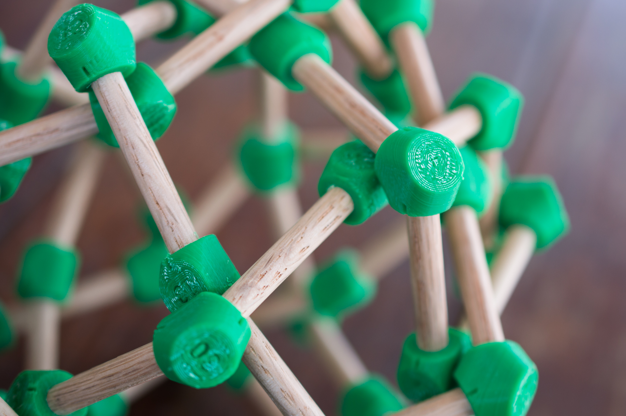
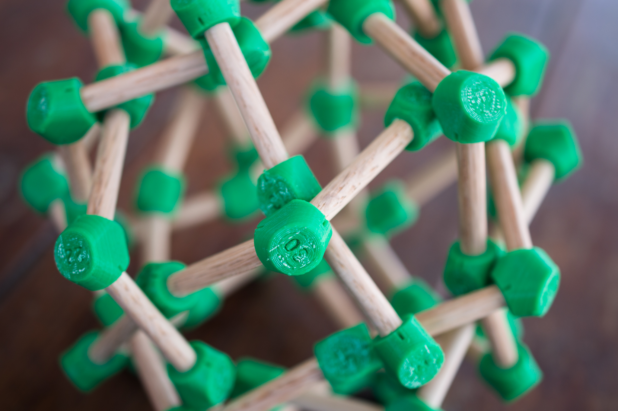
I developed an OpenSCAD script for making the connectors (and ported it to OpenJSCAD for the interactive widget below). The script had a few basic parameters such as the angle between the dowels and an order number so I'd know which connectors to use when. I adapted my 3D knot software to output that information and generated all the connectors. I was hoping that that information would be enough, and that it would just be a challenging puzzle figuring out how to orient the dowels to form it into a knot. It turns out, it's just about impossible without more information (at least for me and my wife and we're pretty good at puzzles). I introduced another parameter called marker angle which puts a mark on either side of each connector. The marks indicate how the connectors should line up with the next and previous connector as shown here:
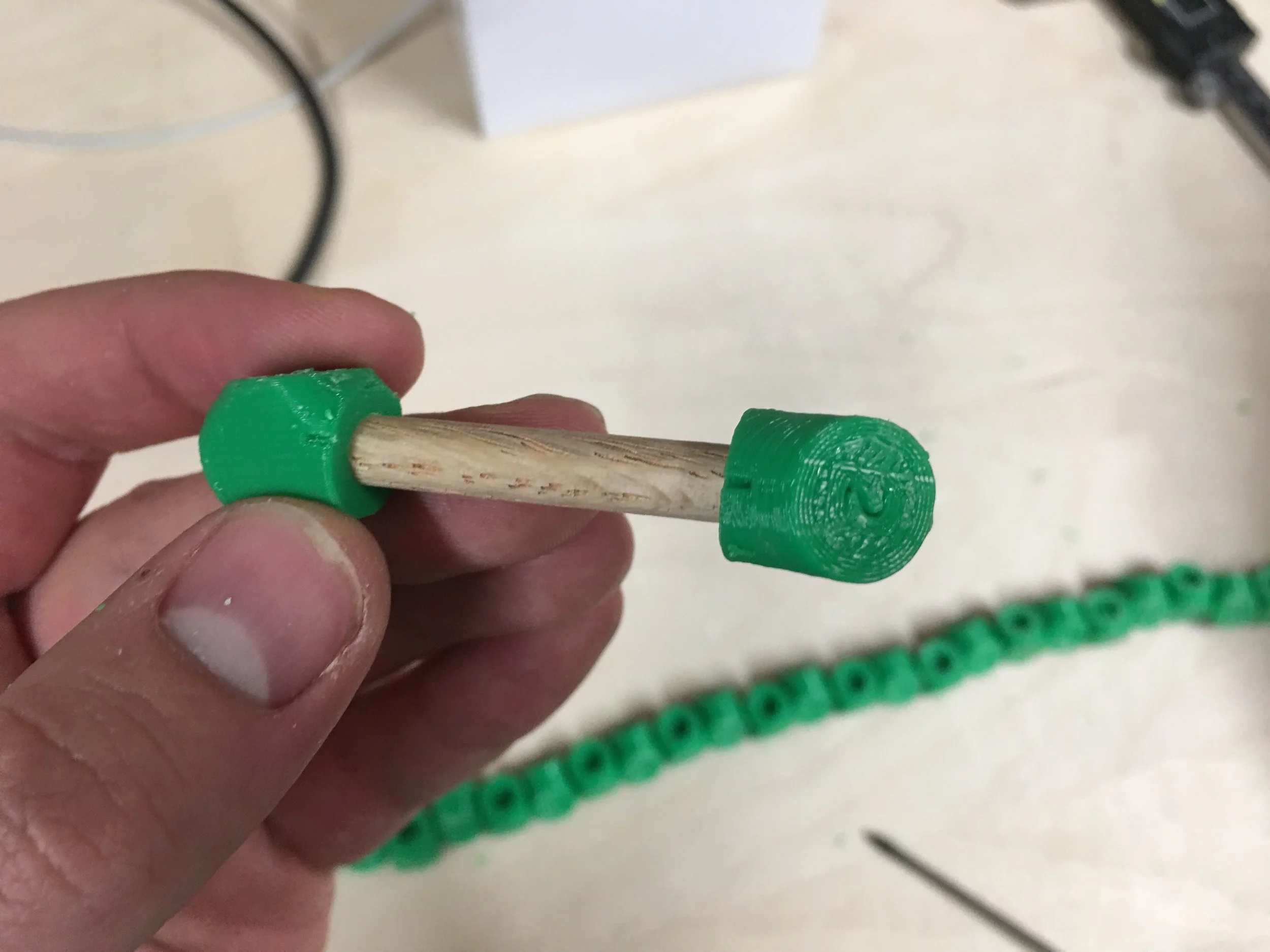
The notches take the guess work out of how the connectors should be aligned.
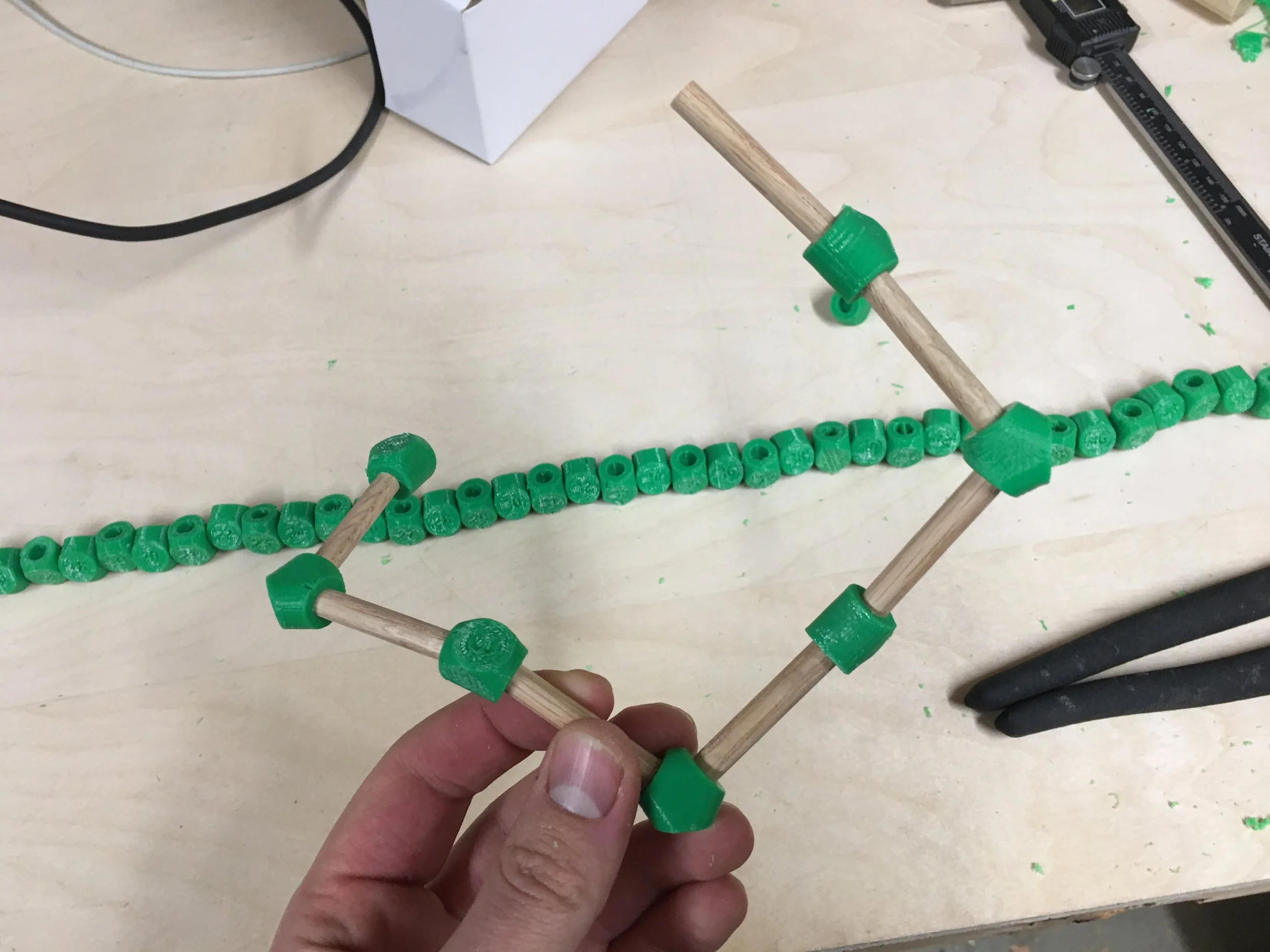
The markers take a lot of the guess work out of how the connectors should be oriented, but the slop from imperfectly aligning them adds up and still makes it a challenging puzzle. The widget below shows how the connectors can be adjusted.
My 3D knot software can now take any knot and output a script which will generate all the necessary connector models. I attempted to assemble my 30 facet globe knot without any further information (just the numbers and the marks on every connector), and still failed to cross over and under the necessary parts. With practice, I think I could do it, but for this test I also had my software print out which numbered connectors crossed over or under other connectors:
11 under 2
20 over 1
25 under 16
26 over 7
29 under 4
30 over 13
31 under 22
34 over 17
35 under 8
38 over 3
39 under 12
40 over 21
43 under 18
44 over 9
45 under 36
46 over 27
47 under 6
48 over 15
49 under 24
50 over 33
51 under 42
52 over 19
53 under 10
54 over 37
55 under 28
56 over 5
57 under 14
58 over 23
59 under 32
60 over 41
1 under 20
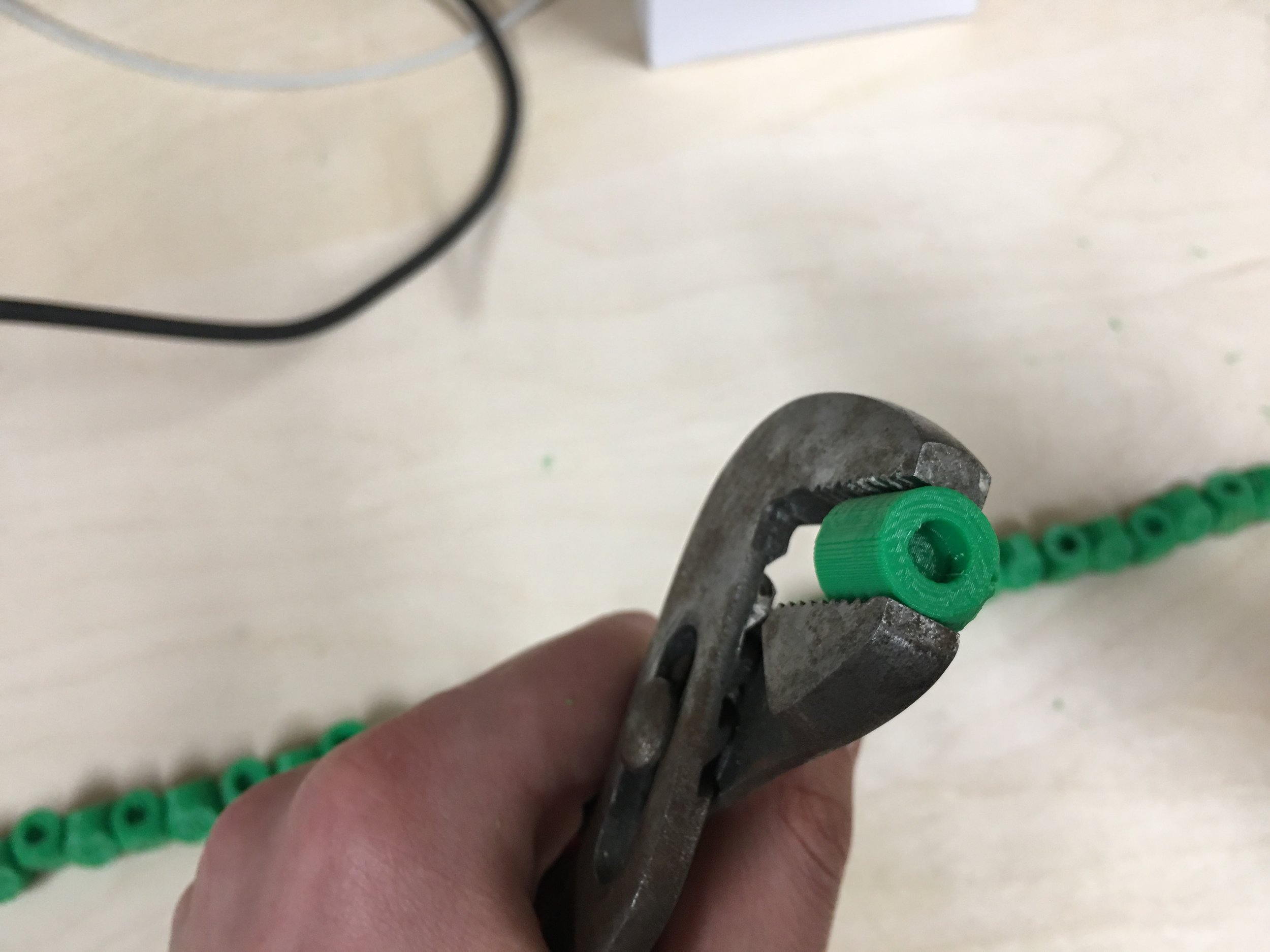
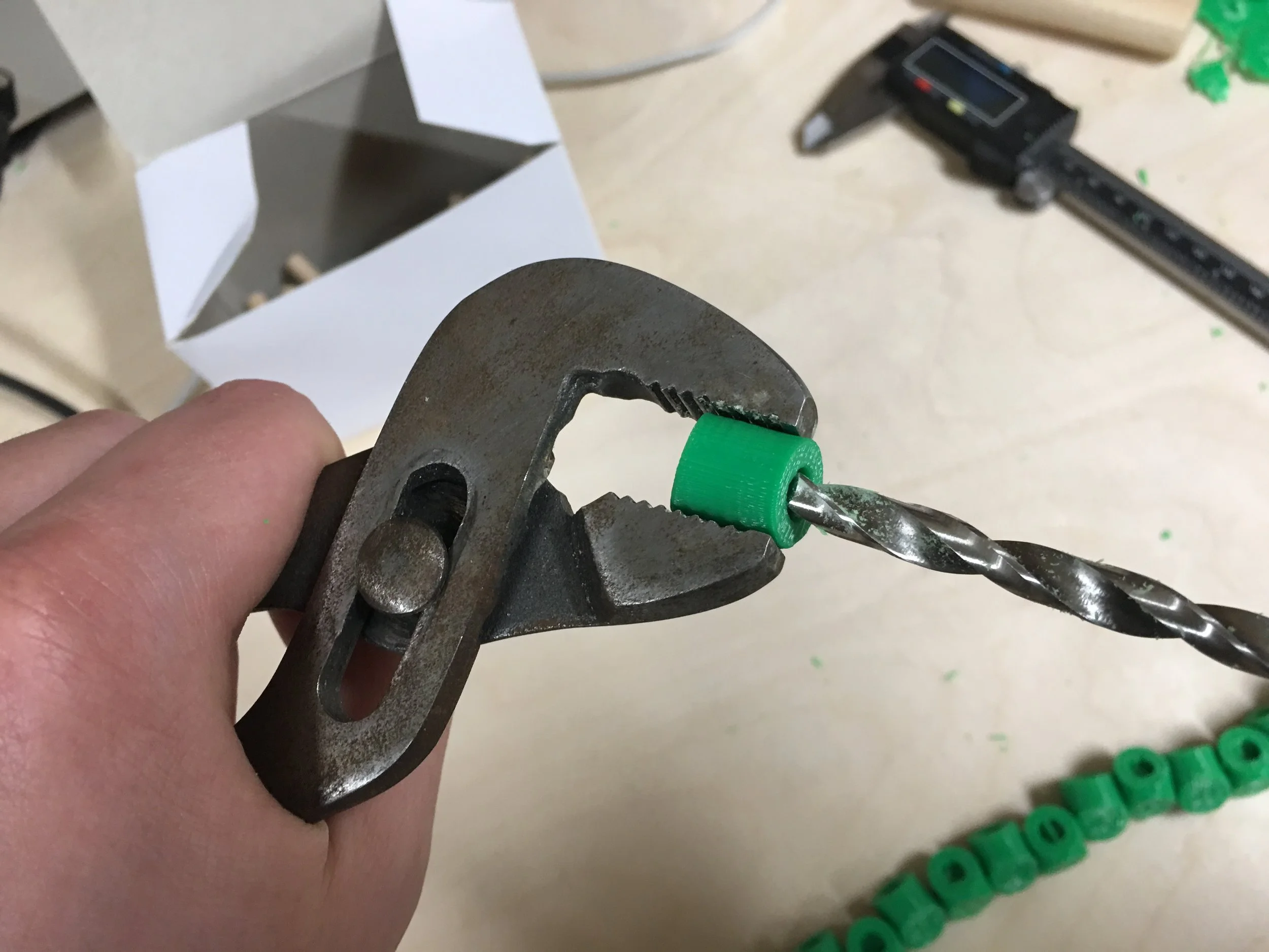
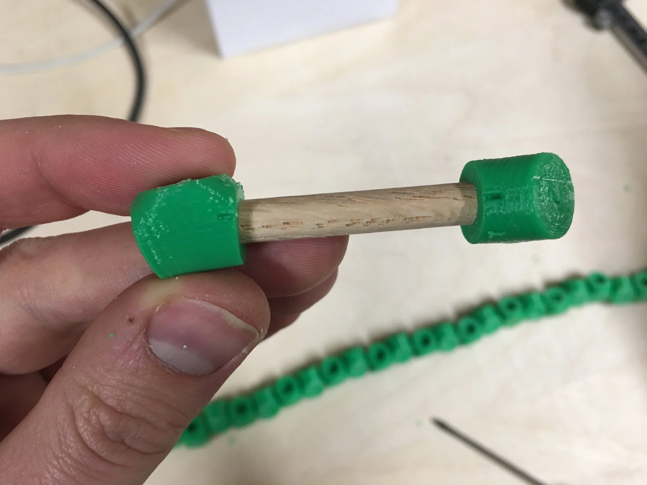
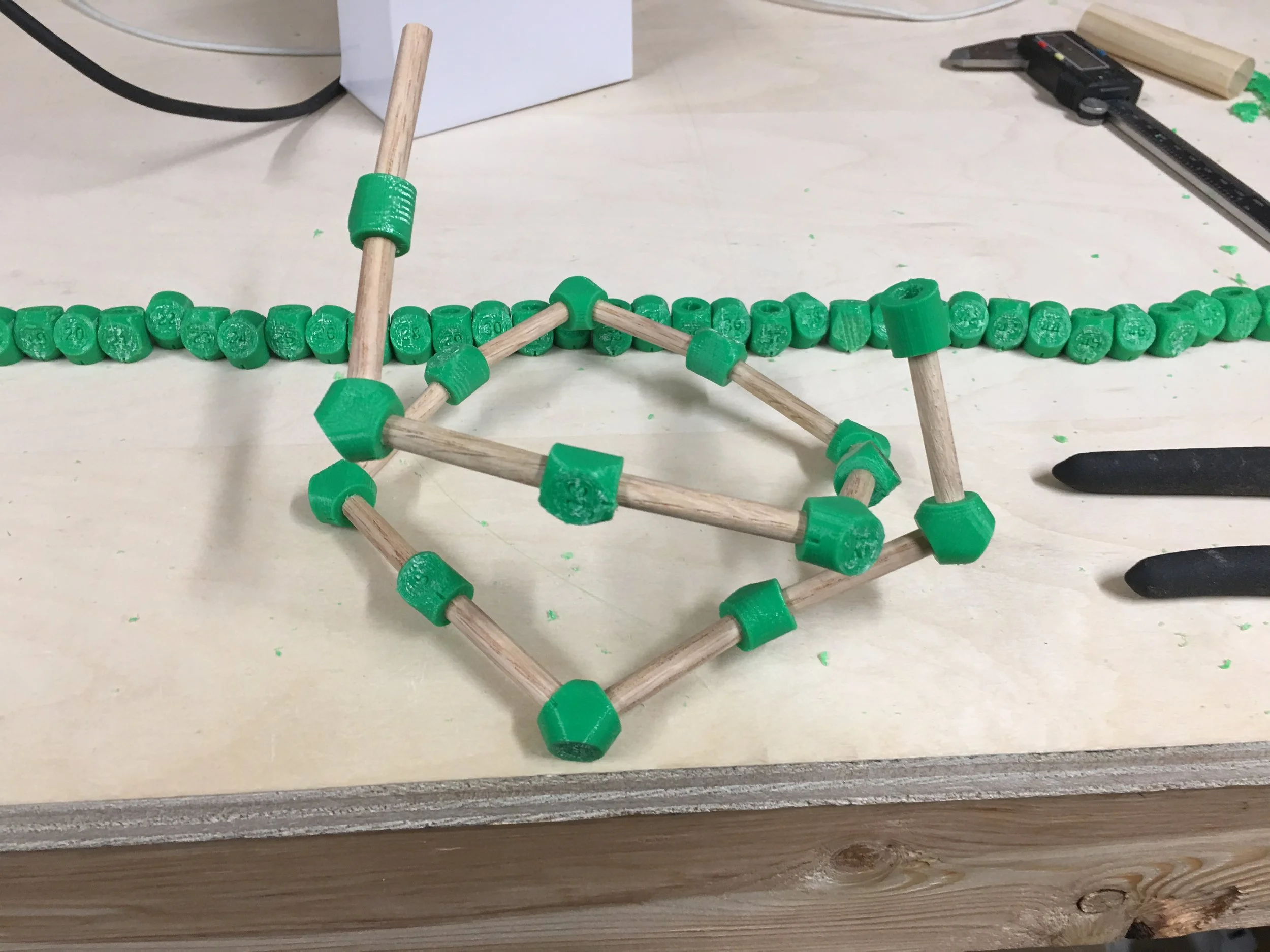
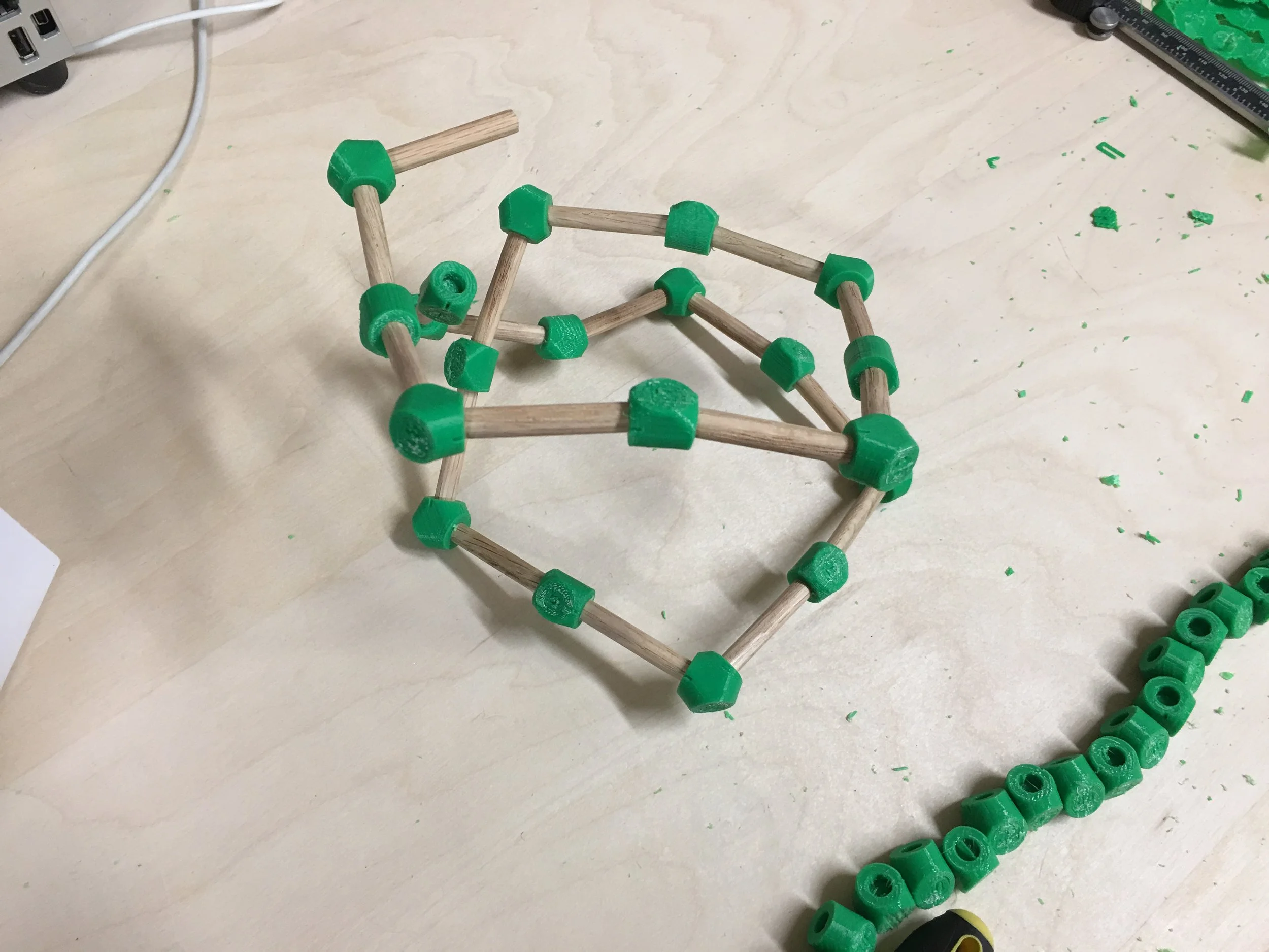
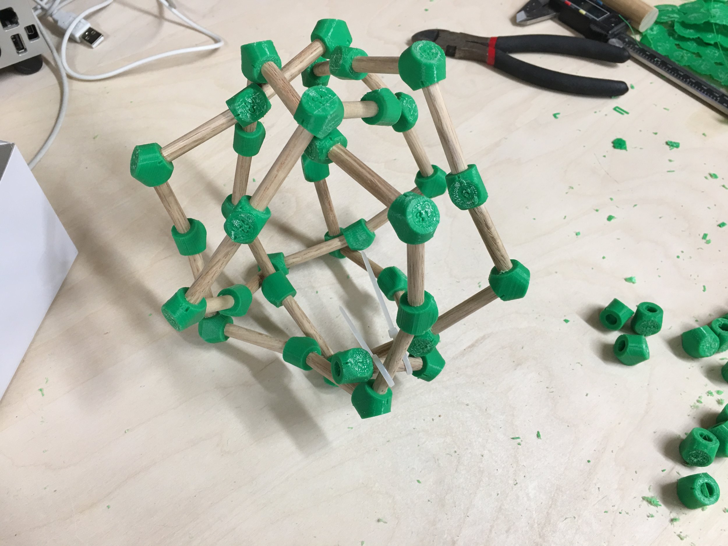
With all of that information, I managed to assemble the knot. Below are some in progress shots. You'll notice that I drilled out my 3D printed connectors. I intentionally left the diameter of the holes exactly 1/4" in diameter, knowing that after a little expansion from printing, they would come out a little smaller. If the dowels are loose at all in the connectors, it makes the puzzle extremely difficult, so instead of worrying about tolerances of my 3D prints, I made them a little small and drilled them out to get a nice snug fit around the dowels. I used my bandsaw to cut 60 dowels to 40mm lengths. My software told me each length exactly, which varied from 39mm-43mm, but I figured 40mm would work and would be easier for me to cut manually. When I get my laser cutter, I might leverage it to do all the cutting for me.

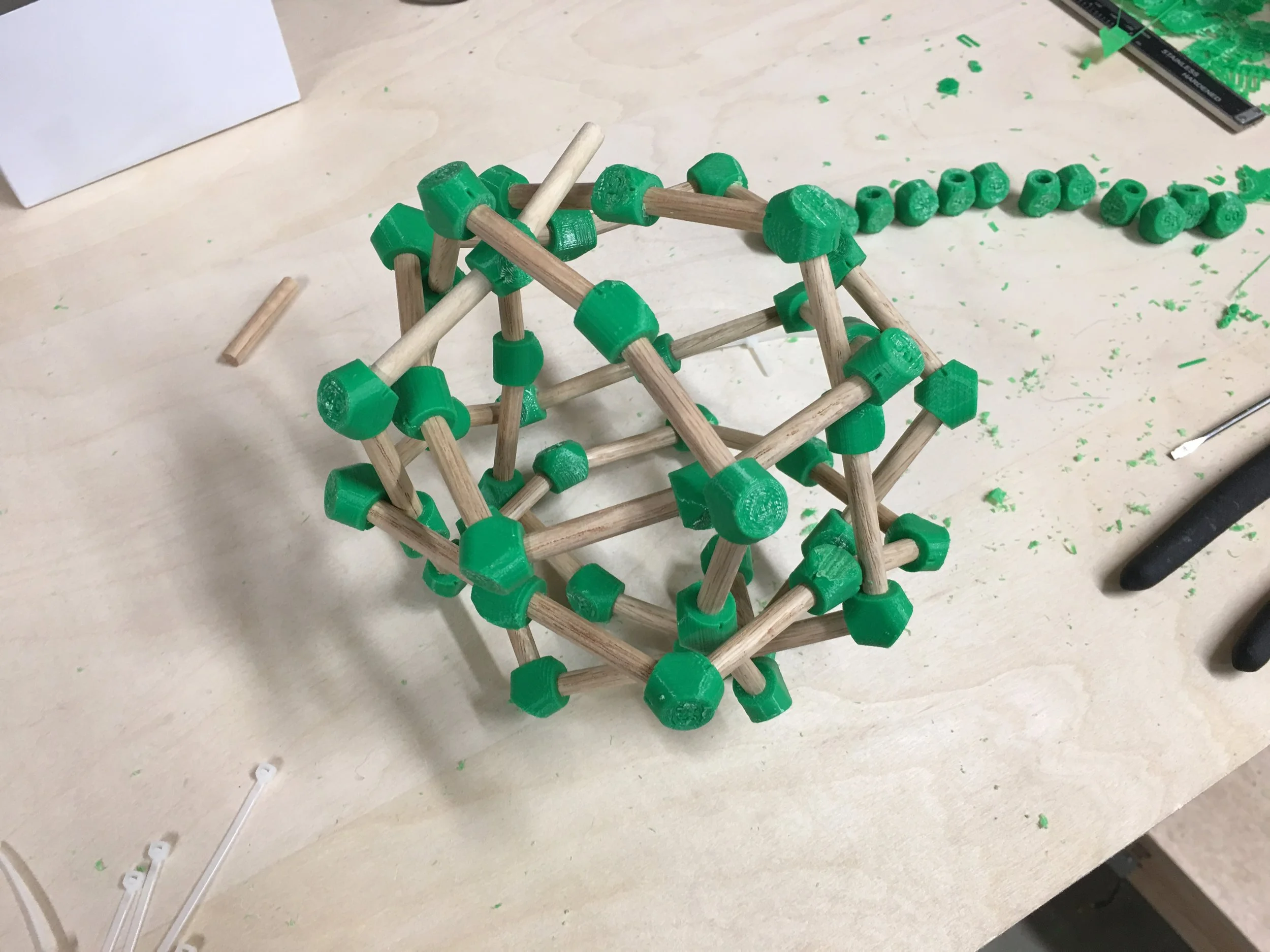
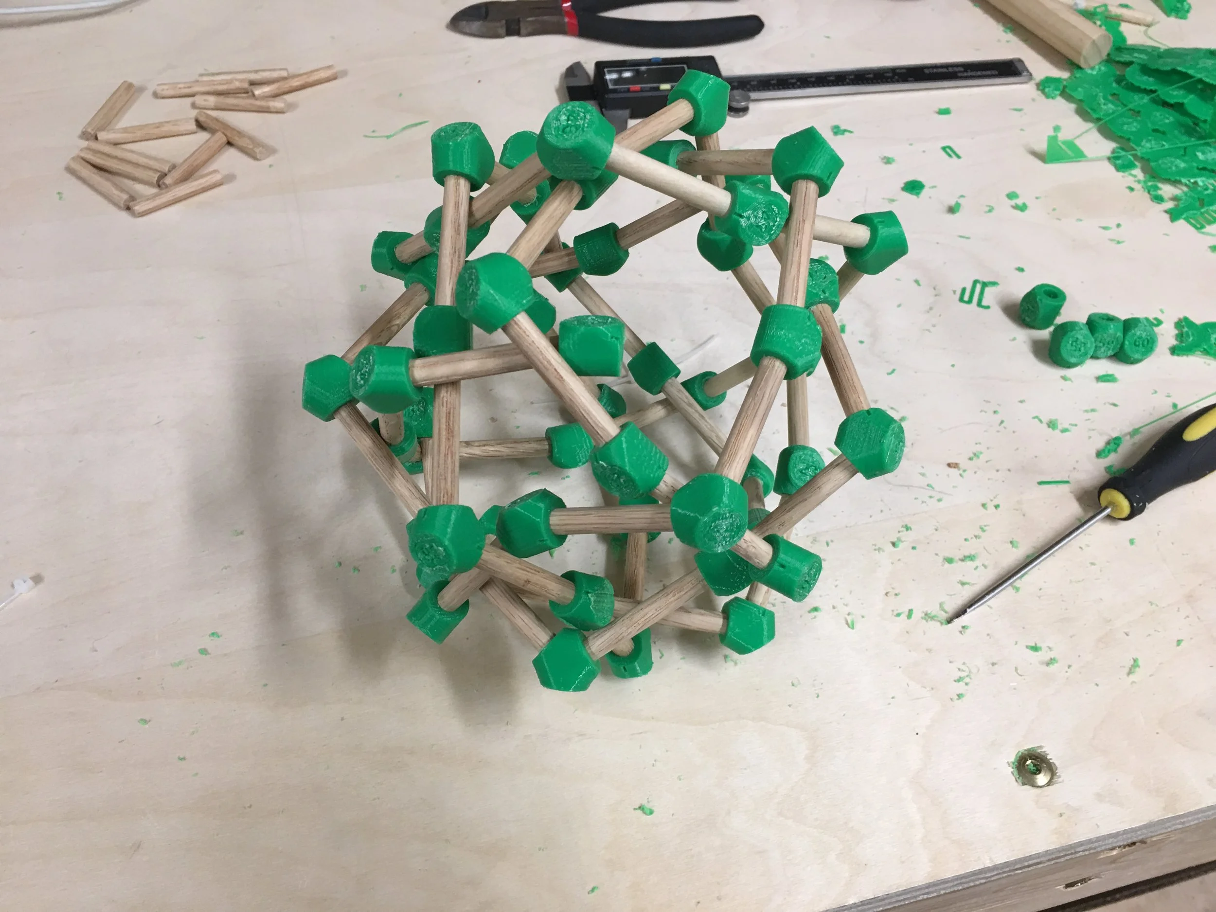
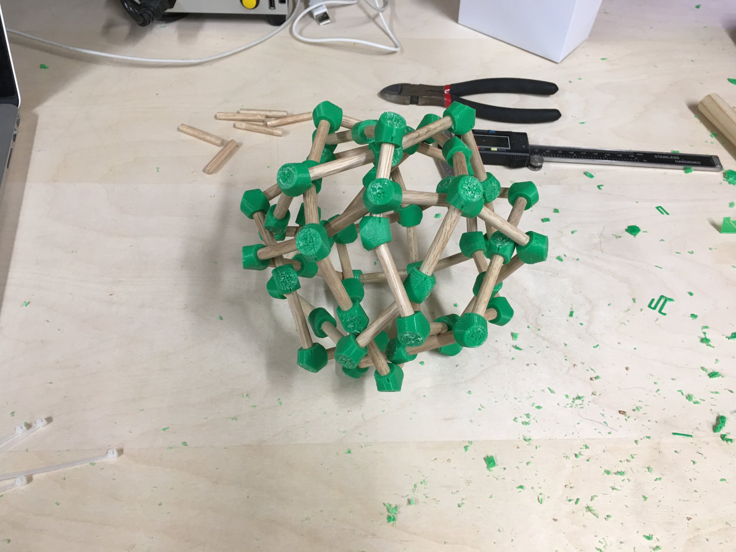
And here are the final results with all the necessary files and instructions to recreate it yourself.


This woven knot ball would make a unique gift as a pendant, keychain or something to fiddle with. A single stainless steel strand weaves and twists around into a continuous loop. The strands don't touch were they cross so they can move a small amount, which causes it to have a distinct chime when rolled on the ground or table.